
Continuous variable wireless data input to RFID reader

a technology of continuous variable wireless data and rfid reader, which is applied in the field of radio frequency identification, can solve the problems of limited ability to distinguish different devices operating simultaneously, limit the life of operation, etc., and achieve the effect of low cos

Inactive Publication Date: 2008-04-10
NBOR CORP
View PDF4 Cites 25 Cited by
  • Summary
  • Abstract
  • Description
  • Claims
  • Application Information

AI Technical Summary

Benefits of technology

[0015]This invention addresses the aforementioned need by providing a simple means to allow continuous data input from RFID tag devices to induction or active type RFID readers. The elements of this invention are of economical design, requiring only three main components: a sensor pad, an antenna and a number of commercially available, low cost transponder tags i

Problems solved by technology

The drawback is that they require battery power that limits the life of operation, unlike induction tags that may operate indefinitely.
These codes are not PN code sequences and have a very limited ability to distinguish different devices operating simultaneously.

Method used


Image

  • Continuous variable wireless data input to RFID reader
  • Continuous variable wireless data input to RFID reader
  • Continuous variable wireless data input to RFID reader

Examples


Embodiment Construction

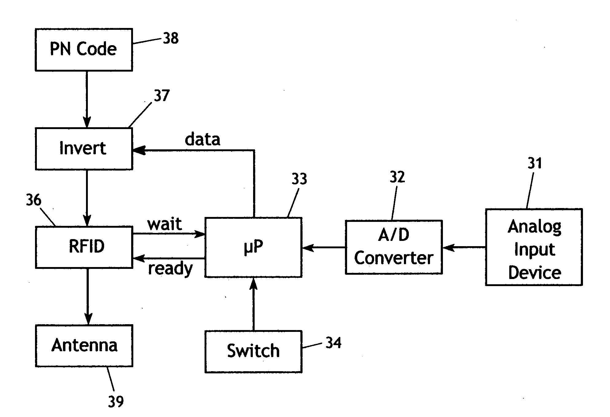
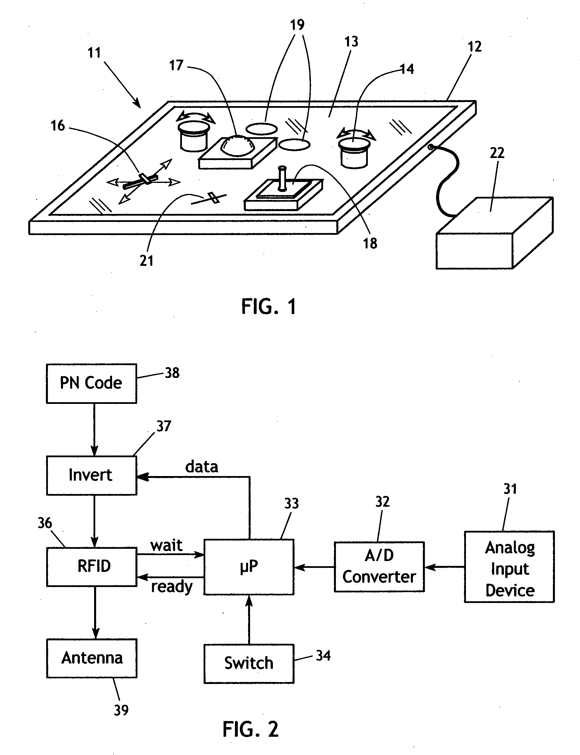
[0028]The present invention generally comprises a simple means to allow continuous data input from RFID tag devices to induction or active type RFID readers. With regard to FIG. 1, a typical proximity RFID reader unit 11 includes a reader housing 12 which surrounds and supports a sensor pad 13. In most cases such a design will consist of a stand-alone sensor pad with a limited number of user input devices that provide a continuous variable output reading and must be transmitted to the RFID reader as digital signals. The user input devices may include knobs 14, faders 16, trackballs 17, joysticks 18 and various types of switches that are physically operated by a user. The sensor pad area may also be used for other forms of continuous input but must rely on the tag for communication. The sensor pad surface and reader housing may also be placed over a LCD screen so that iconic representations 19 and 21 of the knob and fader inputs are displayed on the LCD screen. These iconic represent...


PUM


Abstract

A wireless data input system that has one or more continuous user input devices on a sensing pad or the like, each device connected to a respective individually addressable RFID tags. Each device operates to enable its corresponding individually addressable RFID tag to transmit a unique PN code or the like that is recognized by the RFID reader to identify the respective device and decode the data therefrom.

Description

CROSS-REFERENCE TO RELATED APPLICATIONS[0001]This application claims the priority benefit of the filing date of Provisional Application no. 60 / 849,986, filed Oct. 6, 2006.FEDERALLY SPONSORED RESEARCH[0002]Not applicable.SEQUENCE LISTING, ETC ON CD[0003]Not applicable.BACKGROUND OF THE INVENTION[0004]1. Field of the Invention[0005]This invention relates generally to the field of radio frequency identification (RFID) systems and devices intended to sense the presence of an RFID transponder tag within a sensing field of a reader unit and to read an identification code unique to each such tag, thereby to identify a device associated with the tag using some form of continuous data input. More particularly, this invention is directed to a passive controlling function for accepting the simultaneous and continuous data input from multiple devices using induction or active type RFID readers, and more generally, to wireless data input to RFID readers or devices associated with RFID readers.[0...

Claims


Application Information

Patent Timeline
IPC IPC(8): H04B7/00
CPCH04B5/0043H04B5/02H04B5/0068H04B5/0062H04B5/73H04B5/45H04B5/77H04B5/48
Inventor JAEGER, DENNYLOHBIHLER, ANDREW
Owner NBOR CORP
Learn More