
Drilling tool, a method for drilling a hole and a use of a drilling tool

Inactive Publication Date: 2008-04-03
UNIMERCO
View PDF11 Cites 3 Cited by
  • Summary
  • Abstract
  • Description
  • Claims
  • Application Information

AI Technical Summary

Benefits of technology

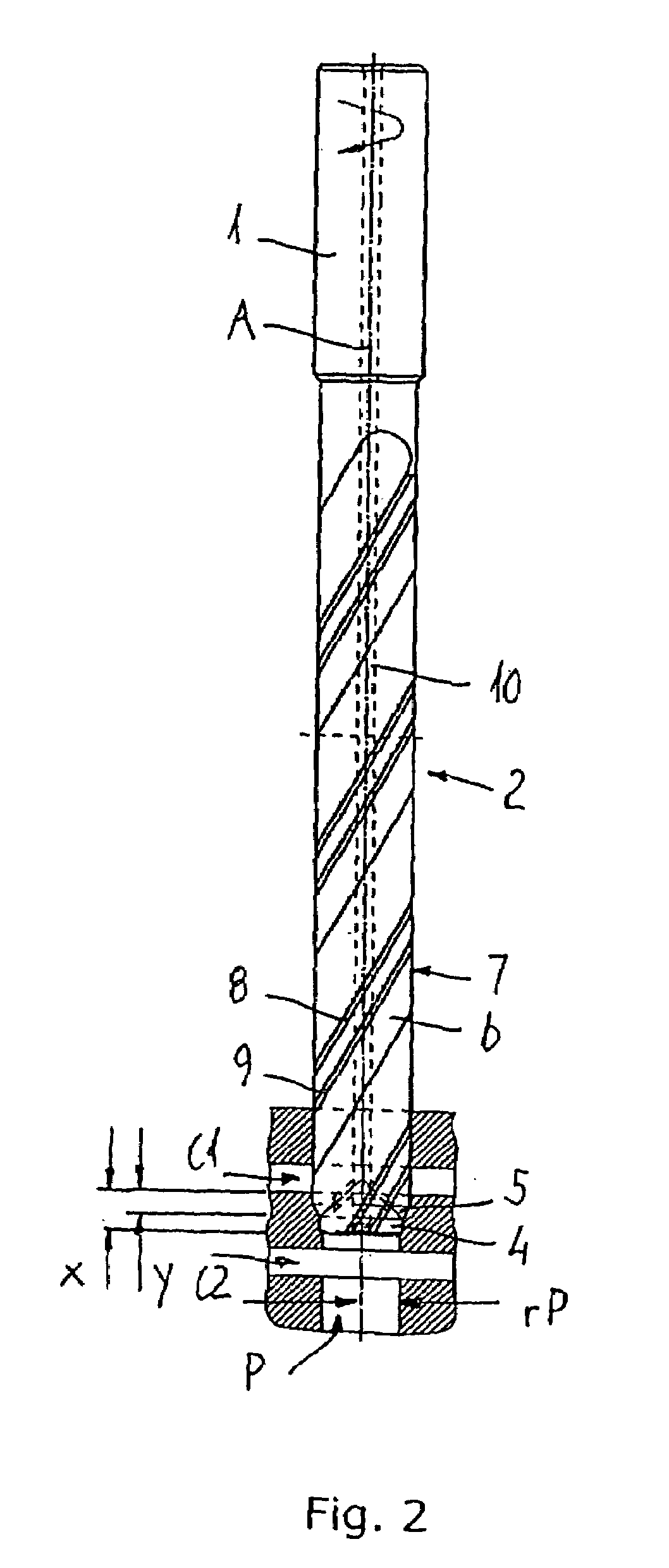
[0010]A drilling tool being provided with said features exhibits a very high accuracy when drilling holes in a work-piece as mentioned earlier. The specially designed tip ensures proper alignment of the tip of the drilling tool when progressing through the still not machined passage. If an ordinary drill tip is used instead of a drill tip according to the invention, the tip of the drill will have a tendency to progress slightly off-set when passing from the increased diameter of the passage to the preliminary diameter of the passage, i.e. when passing the discontinuities of the passage.
[0020]In summary, the drilling tool according to the invention has the technical effect of no ring-like debris being formed. Furthermore, the machining speed, i.e. the time spent for drilling the passage with the drilling tool according to the invention, is faster than when drilling with prior art drilling tools. Up to at least 15% time is saved, possibly up to 30% or even more time is saved. This is due to the fact of a better alignment and accordingly a possibility of faster axial progress of the drilling tool along the passage. If the number of twisted cutting edges is increased from two to three or more, the time spent is very low due to a very good alignment of the drilling tool in the passage. Also, if the number of lands along the twisted cutting edges is two, rather than one, the time spent is also very low, also due to a very good alignment of the drilling tool in the passage.

Problems solved by technology

Such work-pieces, especially when made of a cast material such as cast iron having a brittle texture, are very difficult to work due to several different problems which occur during drilling.
Firstly, proper alignment of a central axis of the finished hole is difficult to obtain due to inaccuracy in the progress of the tip of the drilling tool along the still not machined passage.
Secondly, different types of debris from drilling cast material having a brittle texture may occur when the drill passes from the preliminary diameter to the increasing diameter of the passage.
Thirdly proper alignment of a central axis of the finished hole is furthermore difficult obtaining due to inaccuracy in the progress of the circumferential surfaces of the drilling tool along the already finished hole of the passage.

Method used


Image

  • Drilling tool, a method for drilling a hole and a use of a drilling tool
  • Drilling tool, a method for drilling a hole and a use of a drilling tool
  • Drilling tool, a method for drilling a hole and a use of a drilling tool

Examples


Embodiment Construction

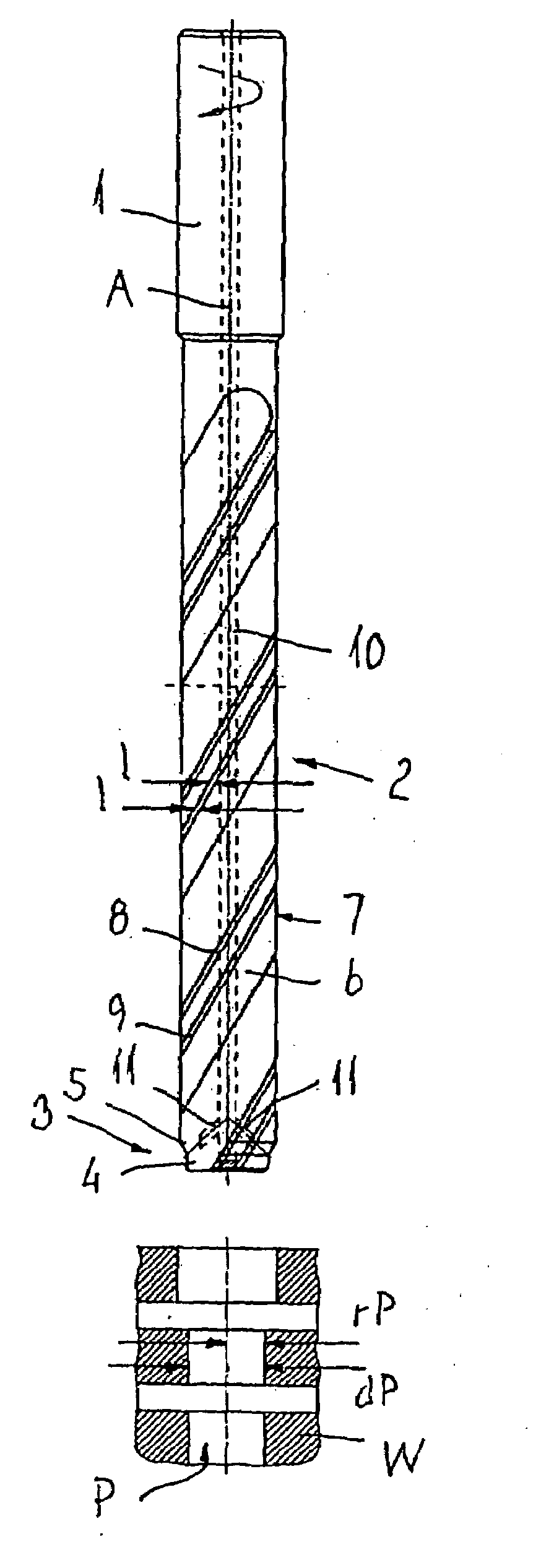
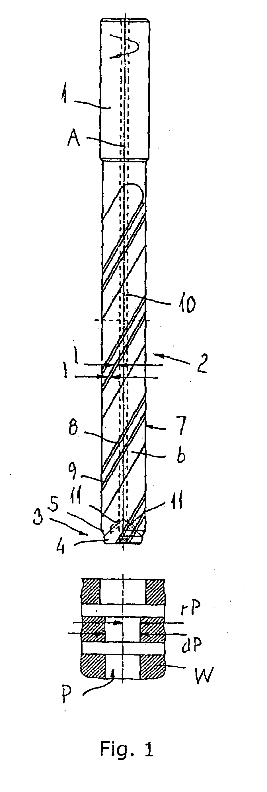
[0026]FIG. 1 is a drawing of an embodiment of a drilling tool having a shaft 1, a drilling head 2 and a tip 3 constituting part of the drilling head 2. The tip is provided with a first cutting element 4 and a second cutting element 5. The first cutting element 4 has the shape of a milling edge, and the second cutting element 5 has the shape of a section of a pointed part of a surface having twisted flutes 6, i.e. the second cutting element has the shape of part of a conventional drilling tool. The remaining part of the twisted cutting edge 6 extends along a circumferential surface 7 of the drilling tool.

[0027]The twisted fluted surface 6 is provided with a first land 8 and a second land 9. Possibly, the twisted fluted surface 6 could be provided with three or even more lands. In the embodiment shown, the first land 8 is a leading land and the second land 9 is a trailing land with respect to the intended rotational direction around a rotational axis A of the drilling tool. The first ...


PUM

PropertyMeasurementUnit
Timeaaaaaaaaaa
Angleaaaaaaaaaa
Angleaaaaaaaaaa

Abstract

A drilling tool of the invention can drill a hole in a work-piece that has a passage, already provided, the diameter of which is to be increased by drilling. In particular, the passage has a discontinuity along the hole, where the diameter of the hole is to be increased along a shorter or longer extension of the hole. To accommodate this task, the drilling tool has a drill head that is provided with (i) at least one first cutting element, extending substantially perpendicular to the rotational axis, and (ii) at least one second cutting element, extending obliquely to the rotational axis. The first cutting element has a first radial extension (r) from the rotational axis, and at least one cutting element has a second radial extension (R) from the rotational axis, such that r is smaller than R.

Description

FIELD OF THE INVENTION[0001]The invention relates to a drilling tool with a shaft and a drill head, said drilling tool during drilling intended for rotation around a rotational axis, and on which drill head a tip with at least two different cutting elements are provided, and said drill head being manufactured from a base body of a base material with a circumferential surface.[0002]The invention also relates to a method for drilling a hole in a work-piece at least partly made of a material having a brittle texture, and where a passage is provided in the in the material having a brittle texture, said passage having a circular-cylindrical extension with a preliminary diameter, said passage having at least one discontinuity, said discontinuity increasing the preliminary diameter of the passage, and where the diameter of the passage is intended for being increased by drilling with a drilling tool along the passage.[0003]Furthermore, the invention relates to use of a drilling tool with a ...

Claims


Application Information

Patent Timeline
IPC IPC(8): B23B51/00
CPCB23B35/00B23B51/0018B23B51/009B23B51/02Y10T408/905B23B2251/04B23B2251/18B23B2251/443B23B2251/54B23B2228/21B23B51/0411
Inventor SORENSEN, JOHNNY PEDERBUNDE, FLEMMING
Owner UNIMERCO
Learn More