
Modular optical components and systems incorporating same

Inactive Publication Date: 2008-04-03
PACIFIC BIOSCIENCES
View PDF68 Cites 110 Cited by
  • Summary
  • Abstract
  • Description
  • Claims
  • Application Information

AI Technical Summary

Benefits of technology

[0004] The present invention is directed to simplified and robust optical components for use in redirecting, deflecting and / or multiplexing optical systems, as well as to the systems that incorporate these components. The components of the invention typically comprise modular optical components (also referred to herein as “optical modules”) in the form of optical plates, prisms or combinations of these that serve to manipulate light without the need for excessively complicated systems of mirrors and lenses, and do so in a manner that prevents or minimizes optical aberrations.
[0006] In another aspect, the invention provides an optical system. In this aspect, the optical system comprises an illumination light source and an analytical substrate. The optical system also comprises an optical train configured to direct illumination light from the illumination light source to at least a first location on the analytical substrate. In this aspect, the optical train comprises a first optical component configured to redirect a beam of light from the illumination light source directed through the first optical component. The first optical component has a first chromatic separation characteristic. The optical train also comprises a second optical component adjacent the first optical component, and the second optical component has a second chromatic separation characteristic that is complementary to the first chromatic separation characteristic, such that chromatic separation of the beam of light imparted by the first chromatic separation characteristic of the first optical component is substantially eliminated by the second chromatic separation characteristic of the second optical component.
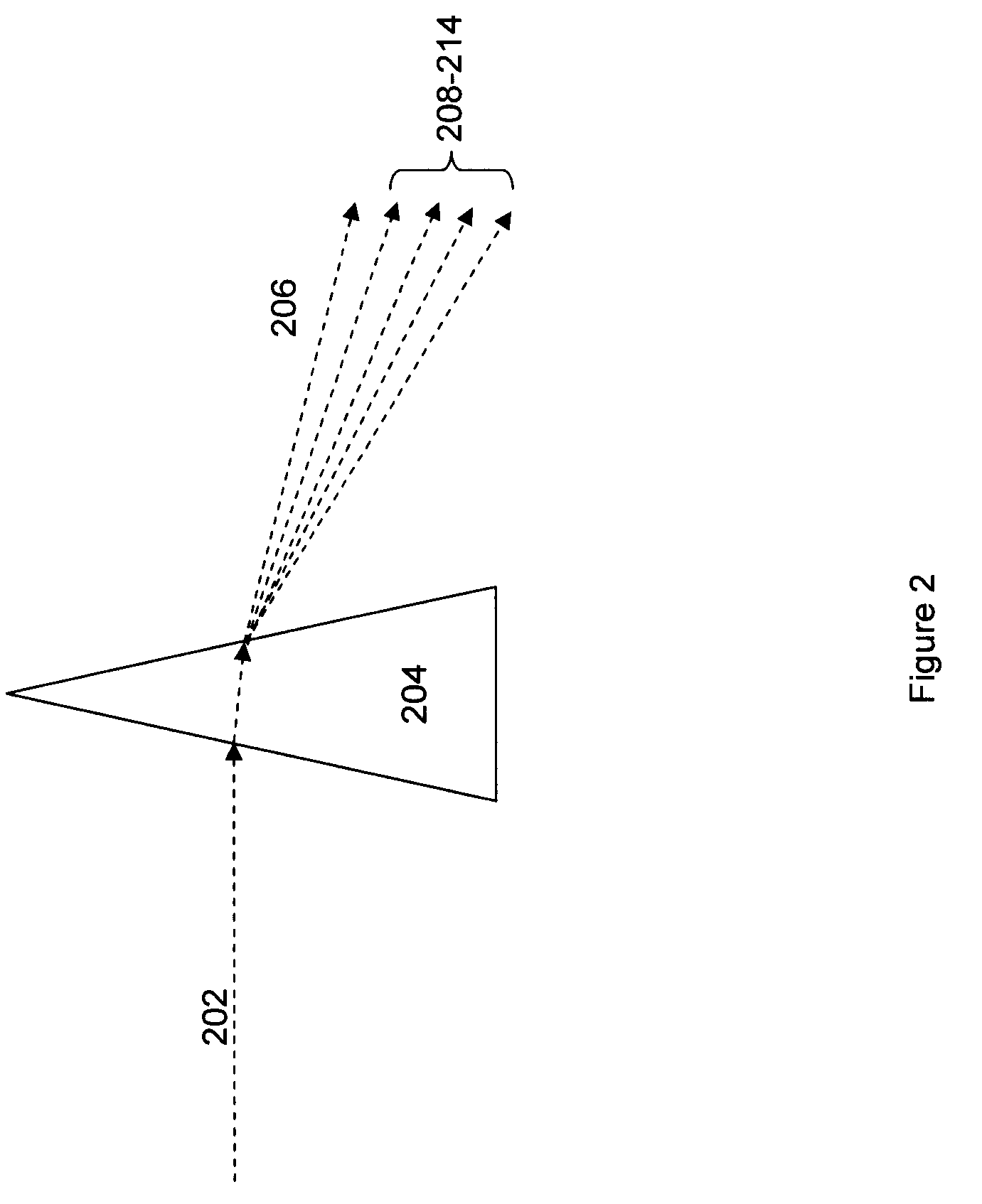
[0009] In yet another aspect, the invention provides a method of achromatically redirecting a path of a light beam. In this aspect, the method includes the step of directing the light beam through a first optical component that is configured to redirect the light beam by a first deflection angle to yield a first deflected light beam, wherein the first optical component has a first chromatic separation characteristic. This method also includes the step of directing the first deflected light beam through a second optical component adjacent the first optical component. The second optical component has a second chromatic separation characteristic that is complementary to the first chromatic separation characteristic, such that chromatic separation of the deflected light beam imparted by the first chromatic separation characteristic of the first optical component is substantially eliminated by the second chromatic separation characteristic of the second optical component, to yield a second deflected light beam.

Problems solved by technology

Such systems typically employ a number of different elements to achieve the various aspects of foregoing and devote a reasonable amount of space and cost to such components.
While the foregoing systems have proven useful in their applications, there is always room to improve upon the functionality, footprint and cost of such systems.

Method used


Image

  • Modular optical components and systems incorporating same
  • Modular optical components and systems incorporating same
  • Modular optical components and systems incorporating same

Examples


Embodiment Construction

[0021] The present invention is generally directed to simplified optical components and optical systems that include such simplified components. By incorporating such components into overall systems, advantages of cost, robustness and overall simplicity are achieved.

[0022] In particular, conventional optical components required to direct and manipulate light in optical systems can involve complex collections of potentially expensive precision optical components to accomplish seemingly minor goals. For example, in directing light beams, mirrors are typically used. Unfortunately, use of such mirrors typically either requires large angle deflections, or multiple serial mirrors precisely arranged, to accomplish minor angles of deflection. Such systems are therefore, either ineffective for certain goals, and / or potentially expensive, complex, and prone to misalignment.

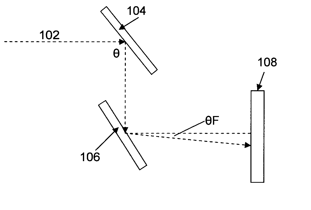
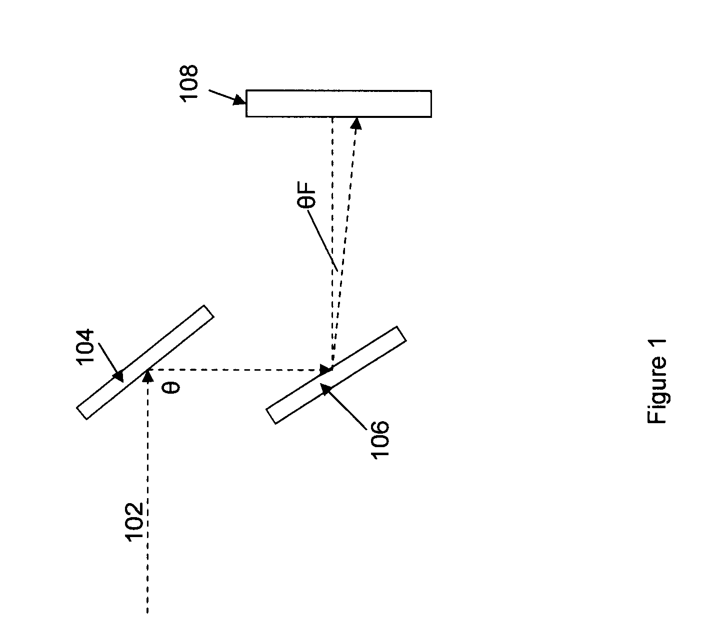
[0023] The foregoing aspect of mirror based deflection systems is schematically illustrated in FIG. 1. As shown, an app...


PUM


Abstract

Modular optical systems employing integrated optical plates, prisms, reflective and semireflective layers that provide less complex, more robust optical systems. The modular systems provide single, or double component optical modules for the redirection, deflection and separation of optical energy for use in optical systems, and particularly optical detection systems for, e.g., fluorescence analysis tools used in the biochemical and chemical analysis industries.

Description

CROSS-REFERENCE TO RELATED APPLICATIONS [0001] This application claims priority to Provisional U.S. Patent Application No. 60 / 847,867, filed on Sep. 28, 2006, the full disclosure of which is incorporated herein by reference in its entirety for all purposes.STATEMENT REGARDING FEDERALLY SPONSORED RESEARCH [0002] Not applicable. BACKGROUND OF THE INVENTION [0003] A large number of systems directed at the optical analysis of samples or materials employ complex optical trains that direct, focus, filter, split, separate and detect light to and / or from the sample materials. Such systems typically employ a number of different elements to achieve the various aspects of foregoing and devote a reasonable amount of space and cost to such components. For example, typical systems employ mirrors and prisms in directing light from its source(s) to a desired destination. Additionally, such systems may include light splitting optics such as beam splitting prisms to generate two beams from a single o...

Claims


Application Information

Patent Timeline
IPC IPC(8): G02B27/14
CPCG01N21/6452G02B27/1006G02B27/148G02B27/126G02B27/144G02B27/106
Inventor DIXON, JOHNLUNDQUIST, PAUL
Owner PACIFIC BIOSCIENCES
Learn More