Differential Geomety-Based Method and Apparatus for Measuring Polarization Mode Dispersion Vectors in Optical Fibers

a technology of optical fiber and dispersion vector, applied in the direction of optical apparatus testing, optical radiation measurement, instruments, etc., can solve the problems of limited accuracy, complex actual curve traced on the surface of the poincaré sphere when the wavelength is varied, and performance of high-speed optical communication systems. , to achieve the effect of reducing the likelihood of error and relatively quick measuremen

Inactive Publication Date: 2008-04-03
AGENCY FOR SCI TECH & RES
View PDF33 Cites 3 Cited by
  • Summary
  • Abstract
  • Description
  • Claims
  • Application Information

AI Technical Summary

Benefits of technology

[0023]The present invention provides a method and apparatus for determining the first and second order PMD vectors of an optical device, such as a single-mode optical fiber, using only a single input polarization state. Advantageously, this permits the measurements to be made relatively quickly, decreasing the likelihood of error due to variation over time of the output polarization state of an optical fiber.

Problems solved by technology

Due to the presence of high-order PMD effects, the actual curve traced on the surface of the Poincaré sphere when the wavelength is varied will typically be more complex.
PMD is one of the most important factors limiting the performance of high-speed optical communications systems.
Most of these measure only the DGD, which is the magnitude of the first order PMD vector, providing only limited accuracy.
This can lead to inaccuracies in the MMM, due to the presence of PDL.
One difficulty with these methods is that they require that measurements be taken with two or more input polarization states, and varying frequencies.
Because of this, taking the measurements is relatively slow.
The long measurement times associated with these methods can cause difficulties because over time, the output polarization state for a fixed input polarization state and frequency can vary in a long fiber.
Thus, by the time the measurement is taken, it may already be inaccurate.
Additionally, errors can be introduced due to the changes in the input polarization states and frequency adjustments.
These errors can introduce further measurement inaccuracies.
This limits its accuracy and utility for making PMD measurements in many high speed communications applications.

Method used


Image

  • Differential Geomety-Based Method and Apparatus for Measuring Polarization Mode Dispersion Vectors in Optical Fibers
  • Differential Geomety-Based Method and Apparatus for Measuring Polarization Mode Dispersion Vectors in Optical Fibers
  • Differential Geomety-Based Method and Apparatus for Measuring Polarization Mode Dispersion Vectors in Optical Fibers

Examples


Embodiment Construction

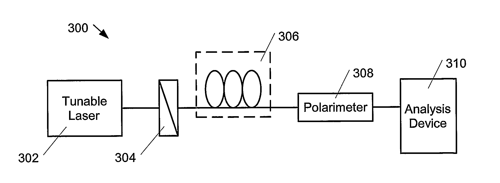
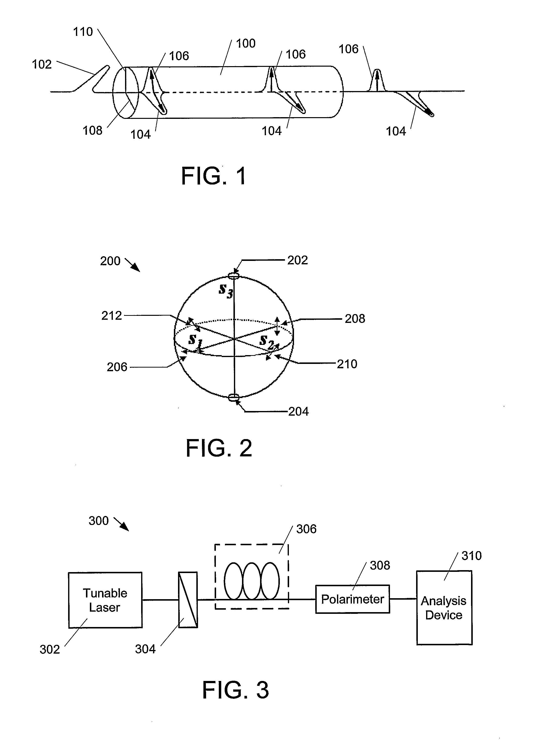
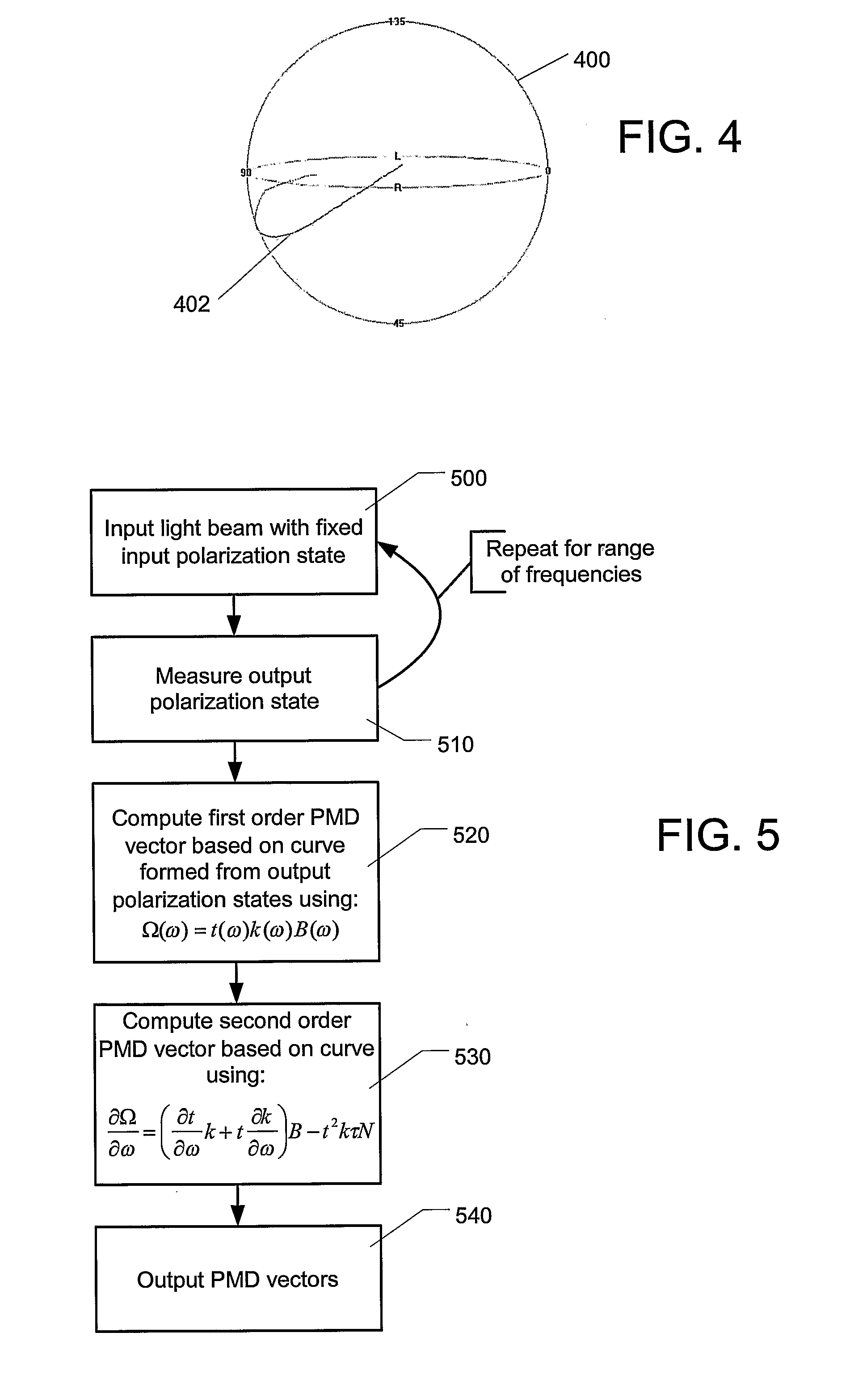
[0034]The present invention relates to determining the first and second order PMD vectors (and, possibly, higher order PMD vectors) of an optical device, such as a single-mode optical fiber, using only a single input polarization state. Advantageously, because only one polarization state is used, the measurements can be performed more rapidly than prior art methods such as Jones matrix eigenanalysis or the Müller matrix method, while producing results that similar in accuracy. Because the methods of the present invention may be performed rapidly, their results may be more accurate than prior art methods, because the output polarization state for a long length of optical fiber may vary over the amount of time that it takes to perform prior art measurements.

[0035]FIG. 3 shows a measurement apparatus that may be used in accordance with the present invention. Measurement apparatus 300 includes a tunable laser source 302, a fixed polarizer 304, the device under test (DUT) 306, a polarime...


PUM


Abstract

A method and apparatus are provided for determining the first and second order polarization mode dispersion (PMD) vectors of an optical device, such as a single mode optical fiber, using only a single input polarization state. This is achieved by passing light beams having a fixed polarization state and frequencies that vary over a range through the optical device that is being tested. The output polarization states of the light beams that have passed through the optical device are measured, and used to form a curve in Stokes space on a Poincare sphere. The shape of this curve is used to approximate the first and second order (and possibly higher order) PMD vectors, using formulas based on differential geometry.

Description

[0001]This application claims the benefit of U.S. Provisional Application No. 60 / 608,005, filed Sep. 7, 2004. The present invention relates generally to fiber optics, and more specifically to the measurement of polarization mode dispersion vectors in optical fibers.BACKGROUND OF THE INVENTION[0002]Polarization mode dispersion (PMD) is an optical effect that occurs in single-mode optical fibers. In such fibers, light from a transmitted signal travels in two perpendicular polarizations (modes). Due to a variety of imperfections in the fiber, such as not being perfectly round, as well as microbends, microtwists, or other stresses, birefringence may occur in the fiber. This birefringence causes the two polarizations to propagate through the fiber at slightly different velocities, resulting in their arriving at the end of the fiber at slightly different times, as seen in FIG. 1. Thus, fibers are said to have a “fast” axis and a “slow” axis. This difference in arrival times is one effect ...

Claims


Application Information

Patent Timeline
Patent Type & Authority Applications(United States)
IPC IPC(8): G01M11/02
CPCG01M11/336H04B10/2569H04B10/07951G01N21/23
Inventor DONG, HUIGONG, YANDONGLU, CHAO
Owner AGENCY FOR SCI TECH & RES
Why Eureka
Try Eureka