Assemble type lever handle

a lever handle and lever handle technology, applied in the field of lever handles, can solve the problems of poor welds, heavy weight, higher cost,

Inactive Publication Date: 2008-04-03
TAIWAN FU HSING INDAL
View PDF0 Cites 7 Cited by
  • Summary
  • Abstract
  • Description
  • Claims
  • Application Information

AI Technical Summary

Problems solved by technology

In general, a conventional lever handle is manufactured by a casting method, and thus causing a heavier weight and incurring a higher cost.
As a result, such arrangement makes the assembling difficult and causes a poor weld.
Furthermore, the forces exerted onto the whole handle are concentrated at the position where the first and second half elements clamp the main body, and thus the first and second half elements may be separated from each other after a long term of use, and the handle cannot be used anymore.

Method used


Image

  • Assemble type lever handle
  • Assemble type lever handle
  • Assemble type lever handle

Examples


Embodiment Construction

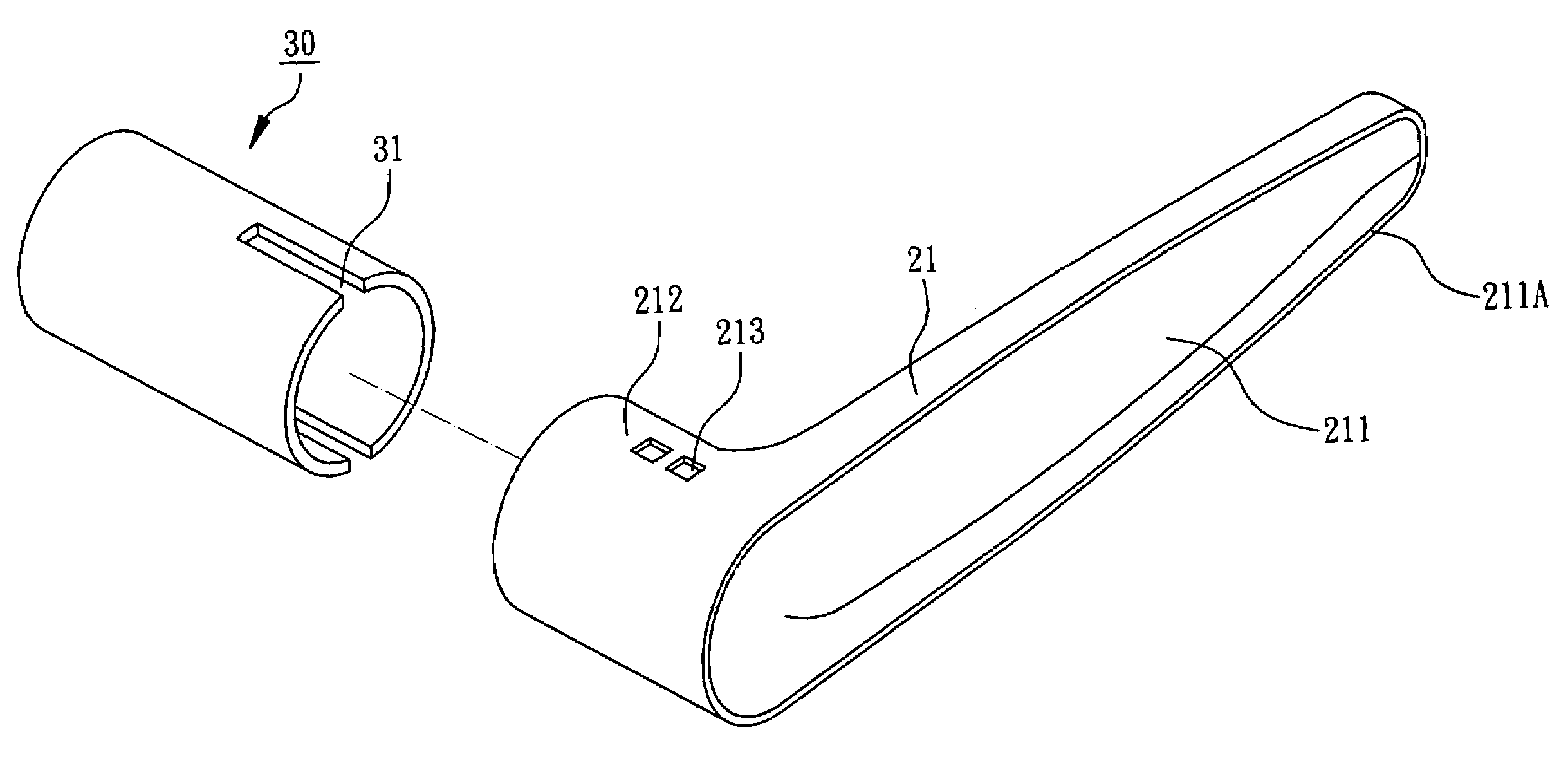
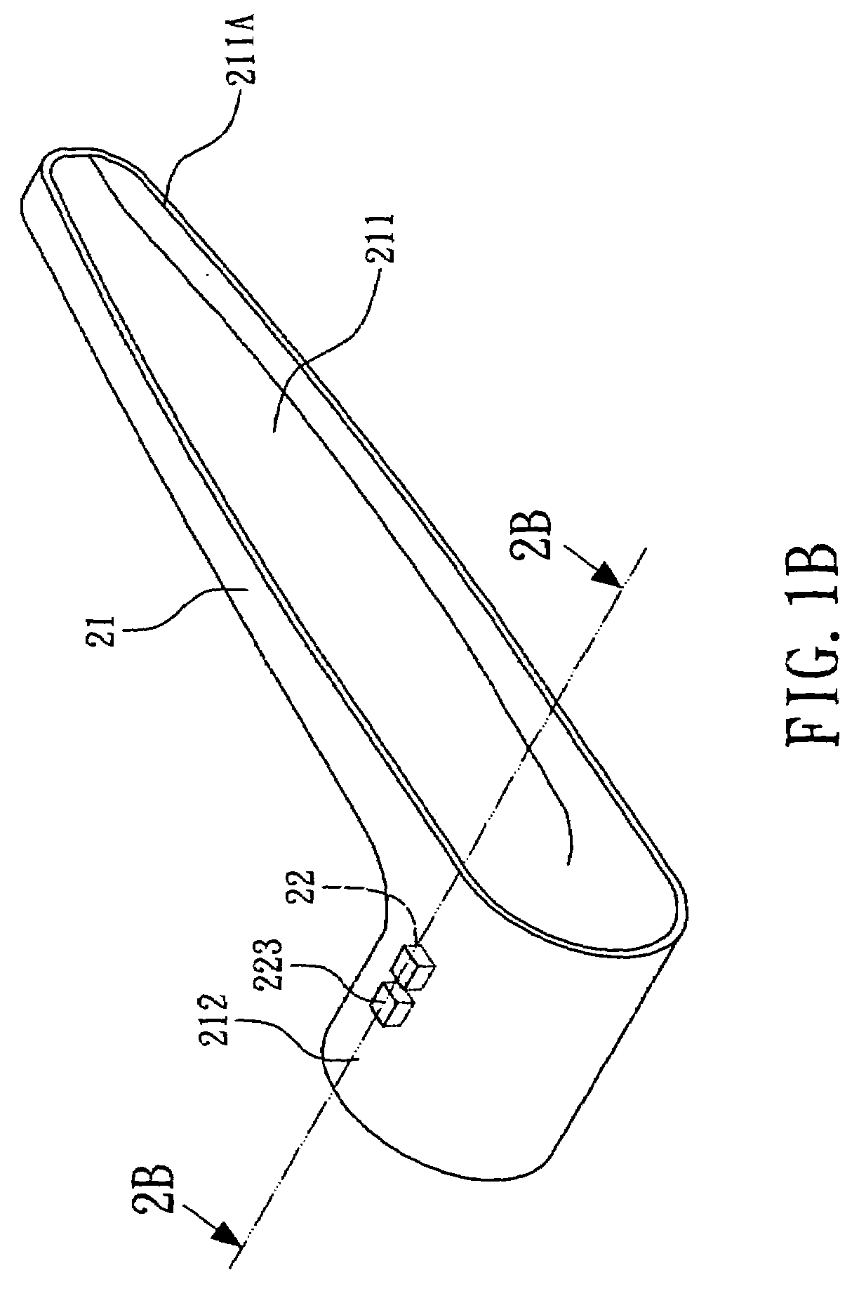
[0014]Referring to FIGS. 1A, 1C, 2A and 2C, a method for manufacturing an assemble type lever handle 20 in accordance with a preferred embodiment of the present invention is disclosed. To begin with, providing a main body 21 as shown in FIGS. 1A and 2A, and the main body 21 has a casing portion 211 and a cylindrical portion 212, and the cylindrical portion 212 is integrally formed by extending from one end of the casing portion 211, and the cylindrical portion 212 is provided for driving a turning shaft 30 to rotate, such that the turning shaft 30 can rotate to drive a pin of a lock to move forward and backward. The cylindrical portion 212 has an internal sidewall 212A, an external sidewall 212B and at least one through hole 213 formed between the internal sidewall 212A and the external sidewall 212B, and the through hole 213 can be a square shape, a rectangular shape, a circular shape, or another geometric shape. Preferably, the main body 21 is made by punching a metal sheet (not s...


PUM


Abstract

An assemble type lever handle comprises a main body and an embedding element. The main body has a casing portion and a cylindrical portion integrally formed by extending from one end of the casing portion. The cylindrical portion has an internal sidewall, an external sidewall and at least one through hole, wherein the through hole forms between the internal sidewall and the external sidewall. The embedding element is inserted into the through hole of the cylindrical portion and has a fixing portion and an internal protruding portion, wherein the fixing portion is fixed to the through hole of the cylindrical portion and the internal protruding portion is protruded from the internal sidewall of the cylindrical portion. In addition, the assemble type lever handle further comprises a cover plate jointed to the casing portion of the main body.

Description

FIELD OF THE INVENTION[0001]The present invention relates to a lever handle, and more particularly to an assemble type lever handle with at least one embedding element.BACKGROUND OF THE INVENTION[0002]In general, a conventional lever handle is manufactured by a casting method, and thus causing a heavier weight and incurring a higher cost. Therefore, a handle as disclosed in R.O.C. Pat. Publication No. 00327911 is provided for improving the difficulties of manufacturing handles. The handle is comprised of a main body, a first half element and a second half element, and the main body is clamped by the first and second half elements, and thus the elements are frequently collided with each other and deformed during an assembling process. As a result, such arrangement makes the assembling difficult and causes a poor weld. Furthermore, the forces exerted onto the whole handle are concentrated at the position where the first and second half elements clamp the main body, and thus the first ...

Claims


Application Information

Patent Timeline
Patent Type & Authority Applications(United States)
IPC IPC(8): B25G3/32
CPCE05B1/003Y10T16/469E05B17/0004E05B1/06
Inventor HUANG, LIEN-HSICHIANG, KUANG-CHUN
Owner TAIWAN FU HSING INDAL
Why Eureka
Try Eureka