
Construction site hole cap for covering holes

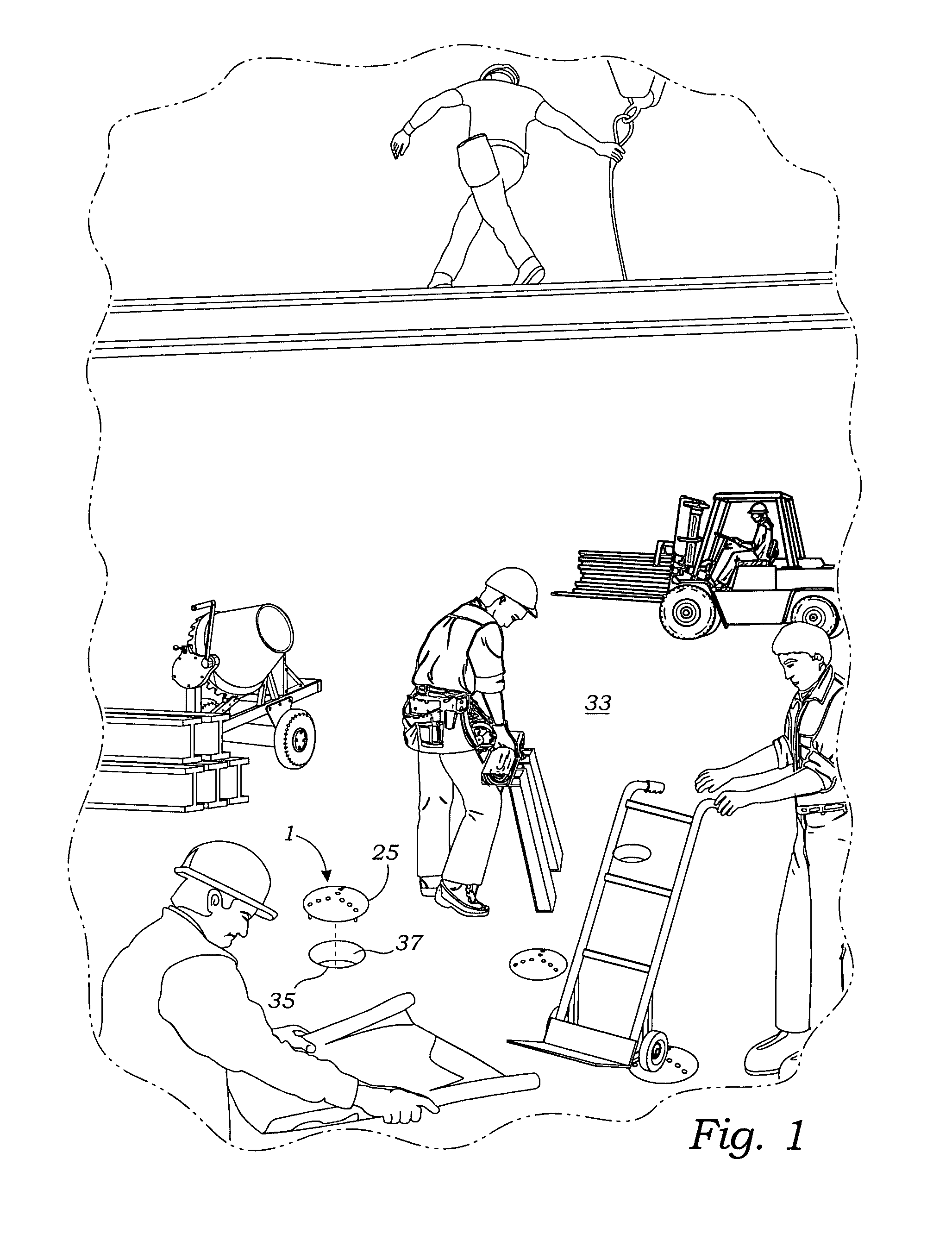
a construction site and hole cap technology, applied in the field of safety devices for construction sites, can solve the problems of inadvertent rolled into the surface holes of wheeled objects such as wheelbarrows, dollies, and other contraptions, and workers face a variety of hazards

Inactive Publication Date: 2008-03-27
BOYD LOUIS
View PDF23 Cites 19 Cited by
  • Summary
  • Abstract
  • Description
  • Claims
  • Application Information

AI Technical Summary

Benefits of technology

[0008]The present invention addresses the aforementioned disadvantages by providing an improved cover for covering holes formed in the walking surfaces at construction job sites.
[0019]It is still another object of the present invention to provide a cover which is adaptable for covering a variety of sized holes.

Problems solved by technology

Workers face a variety of hazards while working on a construction site.
One of the more prevalent hazards is caused by holes formed in walking surfaces.
However, they do provide a tripping hazard.
Moreover, wheeled objects such as wheelbarrows, dollies, and other contraptions can be inadvertently rolled into these surface holes.
Open holes can also be troublesome because various construction equipment such as nuts, bolts, brackets, and tools are prone to fall into such holes.
This presents a safety hazard in multistory buildings to workers below.
Unfortunately, because the stem is sized to fit only one size hole, various sizes of such covers would be required to be maintained on a job site.

Method used


Image

  • Construction site hole cap for covering holes
  • Construction site hole cap for covering holes
  • Construction site hole cap for covering holes

Examples


Embodiment Construction

[0031]While the present invention is susceptible of embodiment in various forms, as shown in the drawings, hereinafter will be described the presently preferred embodiments of the invention with the understanding that the present disclosure is to be considered as an exemplification of the invention and it is not intended to limit the invention to the specific embodiments illustrated.

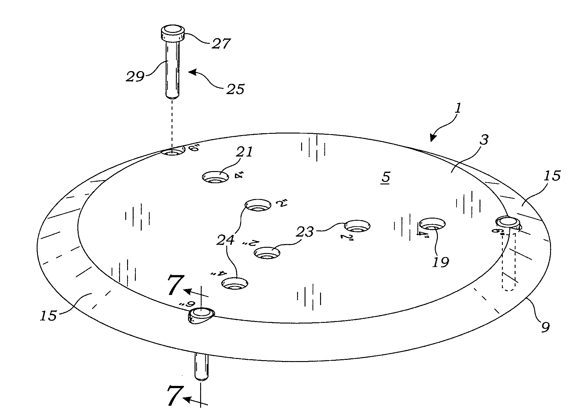
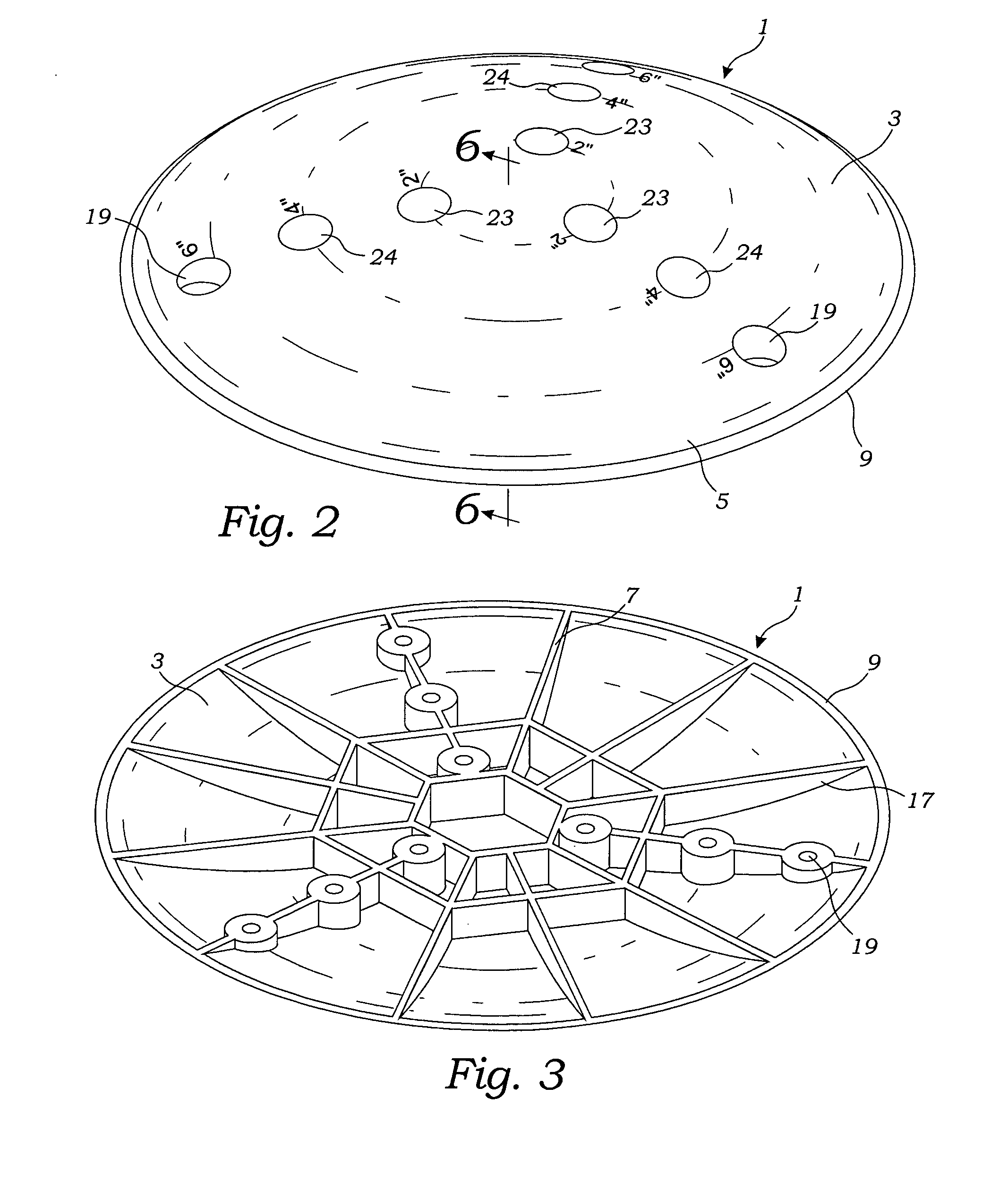
[0032]With reference to FIGS. 1-7, the hole cover 1 of the present invention includes a cap 3 and a plurality of projections 25. The cap 3 includes a top surface 5, a bottom surface 7 and an edge 9. The cap may take various forms. For example, as shown in FIGS. 2-4, the cap may be round to provide a circular edge 9 where the intended hole to be covered is a round hole. Where the hole intended to be covered is rectangular, including square holes, the cap may take a rectangular shape as shown in FIG. 5. In addition, the bottom surface 7 is preferably flat to engage a substantially flat walking surface. Con...


PUM


Abstract

A hole cover is provided for covering holes formed in the walking surfaces at construction job sites. The hole cover includes a cap having a top surface, a bottom surface and an edge. In addition, the cap includes a plurality of bores which project vertically from the cap's top surface to the bottom surface. The hole cover further includes a plurality of projections which are positioned within the bores. Each pin includes a head and shaft. The projections are sufficiently long so that once positioned within the bores, the projections extend downwardly so as to project into a construction site hole which is intended to be covered.

Description

BACKGROUND OF THE INVENTION[0001]The present invention relates to safety devices for construction sites. More specifically, the invention relates to safety devices for covering holes formed in the floor at many job sites.[0002]Workers face a variety of hazards while working on a construction site. One of the more prevalent hazards is caused by holes formed in walking surfaces. These holes are formed in the construction of flooring for the introduction of drains, electrical wiring, water piping, lighting systems, etc. Typically, these holes are only a few inches wide, far too small for an adult to fall into. However, they do provide a tripping hazard. Moreover, wheeled objects such as wheelbarrows, dollies, and other contraptions can be inadvertently rolled into these surface holes. Open holes can also be troublesome because various construction equipment such as nuts, bolts, brackets, and tools are prone to fall into such holes. This presents a safety hazard in multistory buildings ...

Claims


Application Information

Patent Timeline
Patent Type & Authority Applications(United States)
IPC IPC(8): E02D29/14
CPCE02D17/10
Inventor BOYD, LOUIS
Owner BOYD LOUIS
Learn More