
Anonymous tracking using a set of wireless devices

Inactive Publication Date: 2008-03-27
WSOU INVESTMENTS LLC
View PDF35 Cites 20 Cited by
  • Summary
  • Abstract
  • Description
  • Claims
  • Application Information

AI Technical Summary

Benefits of technology

[0011]Problems in the prior art are addressed in accordance with the principles of the present invention in several aspects, by proposing an estimation procedure that can address all of the situations described above. In particular, embodiments of the invention provide a privacy-preserving scheme that enables anonymous estimation of the cardinality of a dynamic set of RFID tags, while allowing the set membership to vary in both the spatial and temporal domains.
[0012]First, the present invention provides, in certain embodiments, an asymptotically-unbiased Enhanced Zero-Based (EZB) estimator, which provides estimates of the tags covered by a single reader. Second, the present invention provides, in certain embodiments, a method for using the EZB estimator to track the dynamics of a tag population in spatial and temporal domains. Third, the present invention provides, in certain embodiments, a method to increase the operating range of an EZB estimator and to reduce the total estimation time, when the magnitude of a tag-set population is unknown. Extensive simulation studies that consider a particular application of anonymous people-tracking will then be discussed, and the effectiveness and accuracy of the proposed schemes will be demonstrated.

Problems solved by technology

However, such efforts have not been fully endorsed by the industry, primarily due to concerns about practicality and costs.
However, without explicit tag-identification schemes (which take a long time to resolve), it is difficult to count the number of all tags in the system in a short period of time.
Strict separation between the two tag sets over successive readings might not be able to be ensured due to (1) a highly-varying radio environment, (2) hard-to-control physical orientation and distance between the reader(s) and the tags, and (3) a need to keep the identities of the tags anonymous.

Method used


Image

  • Anonymous tracking using a set of wireless devices
  • Anonymous tracking using a set of wireless devices
  • Anonymous tracking using a set of wireless devices

Examples


Embodiment Construction

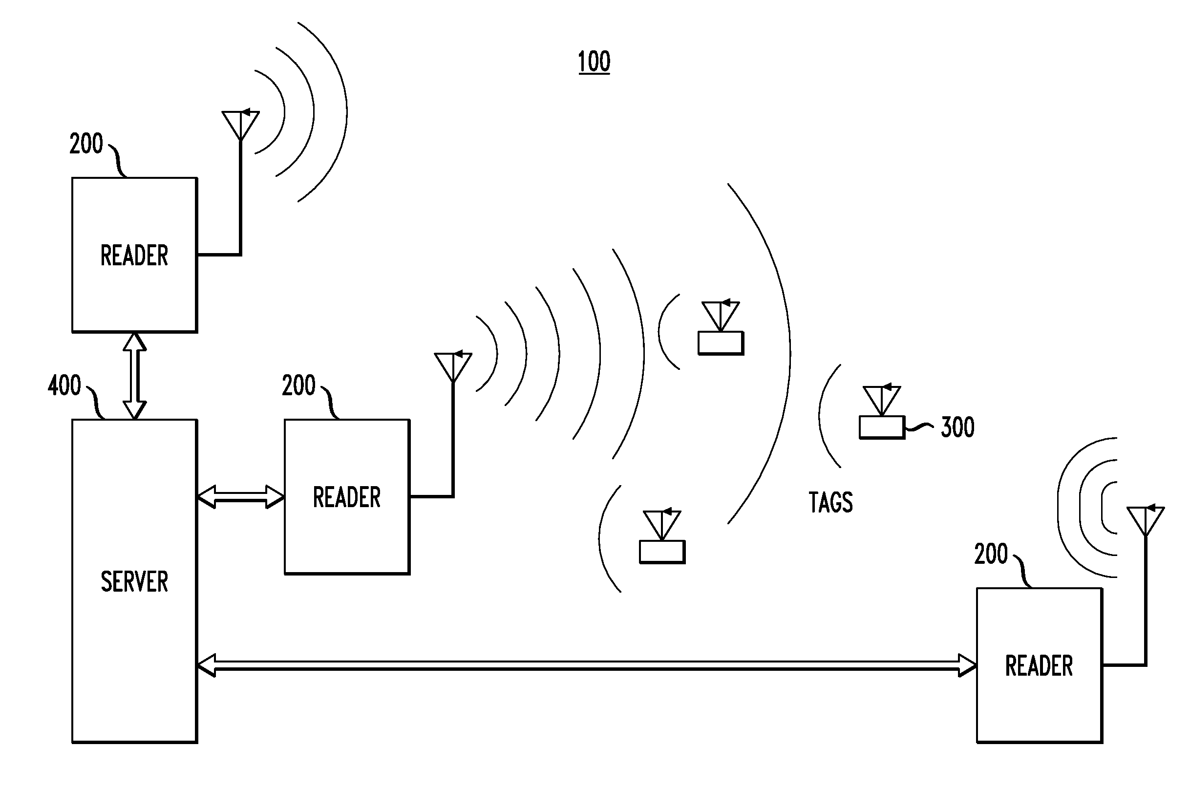
[0024]An RFID-tag and system model, in one embodiment of the invention, will now be introduced. Considering a large field of RFID tags and a set of readers, the set of readers could imply multiple readers reading the field at the same time, or alternatively, a single reader sequentially querying the field at different points in space and / or time, or a combination of both. Such a system adopts a “listen-before-talk” model for the RFID tags, wherein the tags “listen” to the reader's request before they “talk” back. In this scenario, even though tags may have their own unique identifiers, it is not of interest to identify tags uniquely.

[0025]The range of a reader is defined by the set of RFID tags that are capable of transmitting back to the reader. This is because the reader's transmission radius is assumed to be far greater than a tag's transmission radius, and yet, the reader's usefulness is determined only by the number of tags that it can read.

[0026]In a basic ALOHA scheme, as ful...


PUM


Abstract

In one embodiment, a method for estimating the number of tags in a set of tags in a system of tags and readers. The method includes, during each of a plurality of time intervals: (i) transmitting a command requesting that each tag that receives the command determine whether to transmit a reply; and (ii) receiving, in one or more timeslots of a frame corresponding to the time interval, replies from one or more tags. The method further includes providing an estimate of the number of tags in the set of one or more tags based on (i) timeslots in each of the plurality of time intervals that are zero timeslots, i.e., timeslots having no received reply, and (ii) the total number of timeslots in each frame.

Description

CROSS-REFERENCE TO RELATED APPLICATION[0001]This application claims the benefit of the filing date of U.S. provisional application No. 60 / 847,598, filed on Sep. 27, 2006 as attorney docket no. Kodialam 47-16-10, the teachings of which are incorporated herein by reference.BACKGROUND OF THE INVENTION[0002]1. Field of the Invention[0003]The present invention relates to wireless devices, such as radio-frequency identification (RFID) tags, and, in particular, to methods of quickly estimating the cardinality of a dynamically-changing set of wireless devices, i.e., the number of devices in the set, without explicitly identifying the individual devices of the set.[0004]2. Description of the Related Art[0005]Radio-Frequency Identification (RFID) tags are being increasingly used in many applications for identification and tracking purposes. While these devices offer many advantages to consumers, business, and government, privacy advocates have expressed genuine fears that RFID tags can be use...

Claims


Application Information

Patent Timeline
IPC IPC(8): H04B7/00
CPCH04L41/0896H04W74/08H04W24/00H04L43/0882H04J3/02G06K17/00H04B5/48
Inventor KODIALAM, MURALIDHARAN S.LAU, WING CHEONGNANDAGOPAL, THYAGARAJAN
Owner WSOU INVESTMENTS LLC
Learn More