
Tubular structural member with non-uniform wall thickness

a structural member and non-uniform technology, applied in the direction of girders, heat collector mounting/supports, lighting and heating apparatuses, etc., can solve the problems of node moment load or other undesired load applied, affecting the magnitude of actual load in the framing member as compared to the design load magnitude, and the cost and difficulty of assembling such grids

Inactive Publication Date: 2008-03-27
REYNOLDS GLENN A +2
View PDF16 Cites 39 Cited by
  • Summary
  • Abstract
  • Description
  • Claims
  • Application Information

AI Technical Summary

Benefits of technology

"The invention provides a tubular structural member that has a constant size and shape along its length, with flat areas on its exterior surface. The member has a uniform wall thickness, except in certain areas where it is thicker than usual. These areas have aligned holes. The technical effect of this invention is to provide a structural member that is easy to manufacture and use, with improved strength and flexibility."

Problems solved by technology

The reason for the use of pinned connections in DLGs is the cost and difficulty of assembling such grids having moment connections of the framing members at or to the nodes.
Eccentricity at a DLG node causes the node to have moment loads or other undesired loads applied to it.
Clearances at pinned connections in a DLG also can cause the grid framing members to have effective lengths between nodes which deviate from design lengths, thereby affecting the magnitudes of the actual loads in the framing members as compared to design load magnitudes.
It is apparent, therefore, that existing structures and techniques for establishing connections of framing members to nodes in DLGs have deficiencies which adversely affect the load carrying capacities of an overall DLG and of the framing members present in it.
The principal factors effecting the cost of a given DLG are primarily the cost of the materials used to define the grid components and secondarily the cost of labor to assemble those components.

Method used


Image

  • Tubular structural member with non-uniform wall thickness
  • Tubular structural member with non-uniform wall thickness
  • Tubular structural member with non-uniform wall thickness

Examples


Embodiment Construction

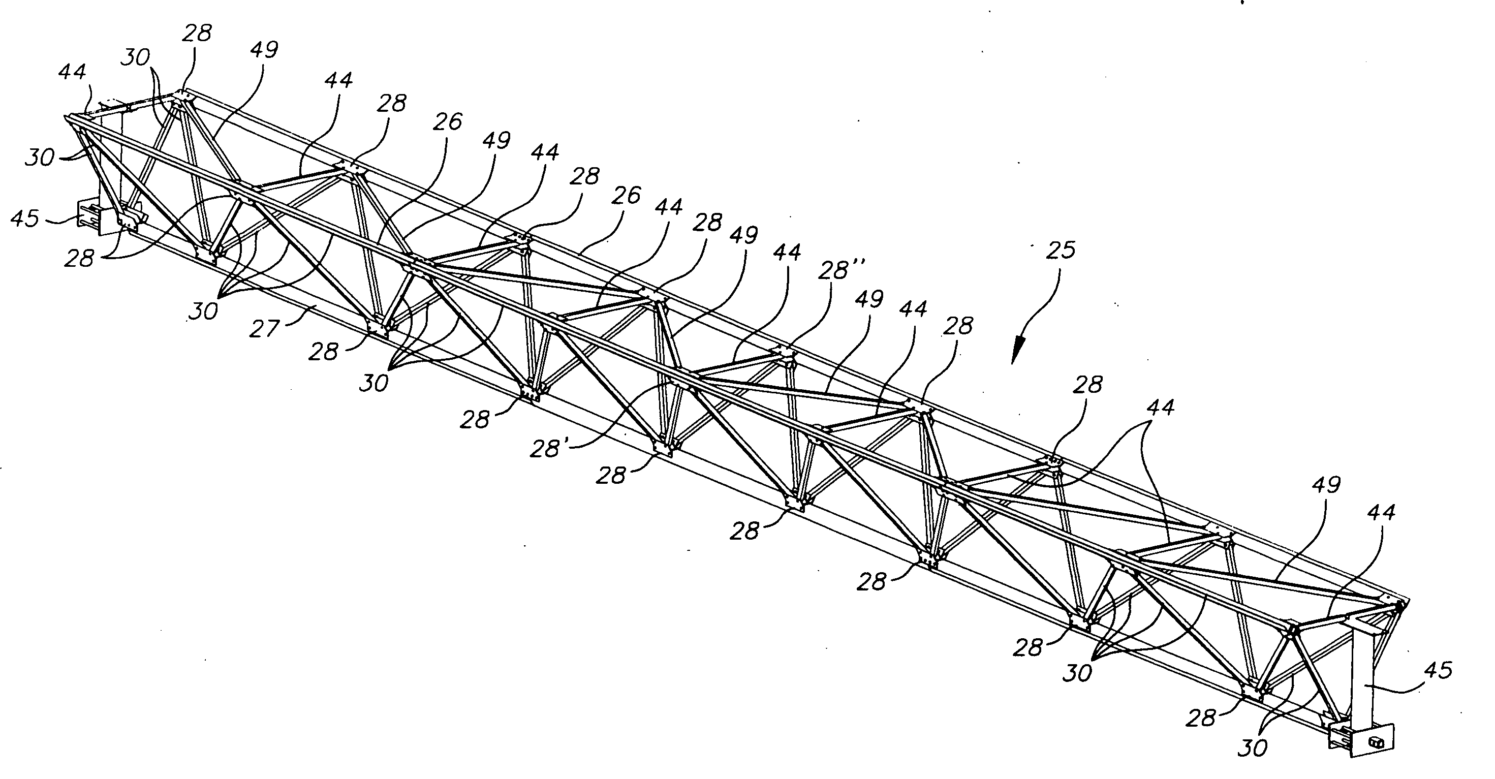
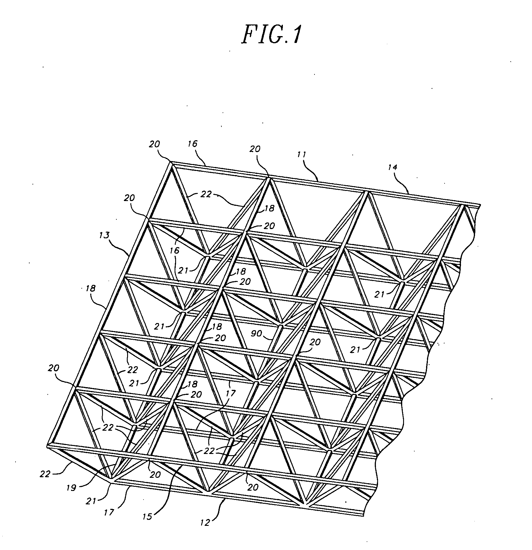
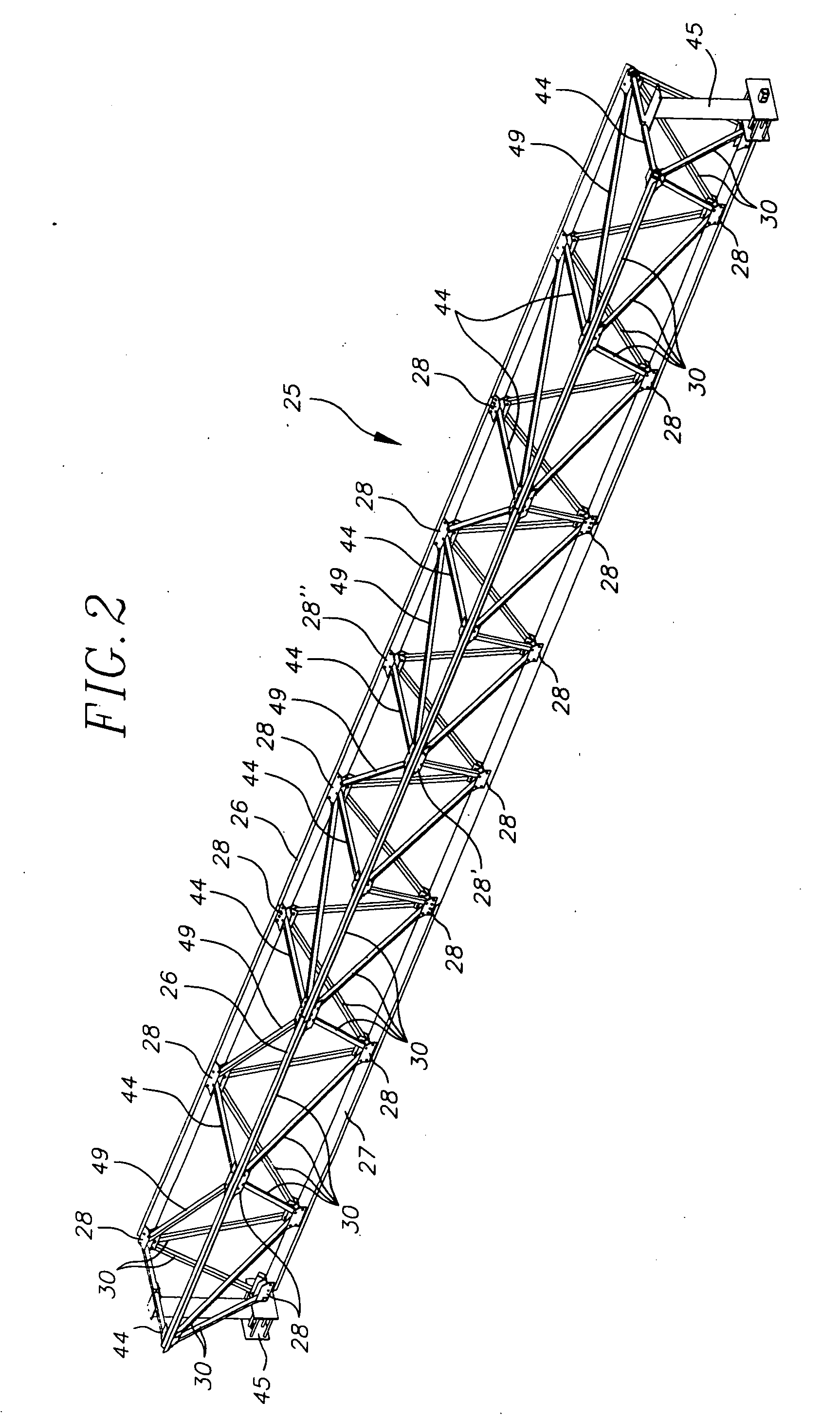
[0050]FIG. 1 is a perspective view of a portion of a rectilinearly subdivided DLG space frame 10. Frame 10 is composed of framing members which are disposed to define top 11 and bottom 12 layers of the frame and to interconnect those layers in an arrangement which causes frame layers 11 and 12 to be in spaced parallel relation to each other. Layers 11 and 12 can also be called grids, hence the name double layer grid (DLG) for the type of space frame shown in FIG. 1.

[0051] The framing members of DLG 10 are comprised by chords which are interconnected to define top and bottom layers 11 and 12 of the DLG which has an end 13 and opposite sides 14 and 15. The chords which extend along the length of the DLG can be and preferably are continuous (subject to limitations on the lengths available) and, for present purposes, are called major chords. Thus, DLG 10 includes upper major chords 16 and lower major chords 17. In each layer of DLG 10, the upper and lower major chords are interconnecte...


PUM


Abstract

A tubular structural member has substantially constant cross-sectional size and configuration along its length between its opposite ends. The member has a pair of parallel oppositely aligned flat areas in its exterior surface. The member has substantially uniform wall thickness except in a selected portion of each the opposing areas where the member's wall thickness is a selected amount greater than the uniform wall thickness. The increase wall thickness preferably is manifested in the interior of the tubular member. The cross-sectional area of the member can have orthogonal neutral axes, and the exterior dimension of the member along one of those axes can be greater than the exterior dimension of the member along the other of those axes which is normal to the exterior flat areas; the amount and distribution of the thickening of the member's walls over the uniform thickness can be defined to cause the section modular of the member about each of the neutral axes to be substantially equal.

Description

CROSS-REFERENCE TO RELATED APPLICATION [0001] This application is a division under 35 U.S.C. § 120 of co-pending application Ser. No. 11 / 525,721 filed Sep. 22, 2006, and claims the priority of only that Application and not the priority of any application filed before application Ser. No. 11 / 525,721.FIELD OF INVENTION [0002] This invention pertains to tubular structural members. More particularly, it pertains to tubular structural members having non-uniform wall thickness having particular utility in pinned connections. BACKGROUND OF THE INVENTION [0003] A space frame is a network of structural framing members, such as tubes, interconnected at multi-member connection points (commonly called “nodes”) in such a way that the whole structure behaves as one structural element. By contrast, in the typical framing of beams and columns, as in buildings, structural elements often act independently of each other and can have completely separate force paths. [0004] Two broad classes of space fr...

Claims


Application Information

Patent Timeline
Patent Type & Authority Applications(United States)
IPC IPC(8): E04C3/02
CPCE04B1/19E04B1/1903E04B2001/1933E04B2001/1936E04B2001/1975E04B2001/1984E04H12/00E04C2003/0495F24J2/52F24J2/5233H01Q15/18Y02E10/47E04B2001/199F24S25/00F24S25/13
Inventor REYNOLDS, GLENN A.HACKBARTH, DEAN R.CURTIS, GARY N.
Owner REYNOLDS GLENN A
Learn More