
Three-dimensional scanner with RFID

a three-dimensional scanner and rfid technology, applied in the field of three-dimensional scanners with rfid, can solve the problems of poor manageability, inability to match model data to possibly defective instruments in verification, and inability to accurately represent the relationship between the actual instrument and the anatomical structure to be treated, so as to achieve the effect of reducing time and increasing process reliability

Active Publication Date: 2008-03-20
BRAINLAB
View PDF6 Cites 37 Cited by
  • Summary
  • Abstract
  • Description
  • Claims
  • Application Information

AI Technical Summary

Benefits of technology

This patent describes an improved way to verify, calibrate, and measure instruments used in computer-assisted surgeries. It helps make these procedures faster and more reliable by making sure that the instruments work properly. The technique works well even if the instruments have complicated shapes, which means they could be designed for specific uses without being too difficult to prepare.

Problems solved by technology

The technical problem addressed in this patent text is the difficulty of accurately tracking the position and orientation of surgical instruments and their functional elements during computer-assisted surgeries using navigation systems. This is due to the challenge of accurately calibrating the reference systems used to track the instruments, which can change in time due to wear and tear or being mechanically burdened. The patent text describes various methods for calibrating the instruments, including manufacturing documents, surveying the instrument and reference device, and using a navigable calibration tool. However, these methods have limitations and can negatively impact the operation time. The patent also mentions the use of marker means that can be detected by a detection device to establish the position of the instrument relative to the detection means.

Method used


Image

  • Three-dimensional scanner with RFID
  • Three-dimensional scanner with RFID
  • Three-dimensional scanner with RFID

Examples


Embodiment Construction

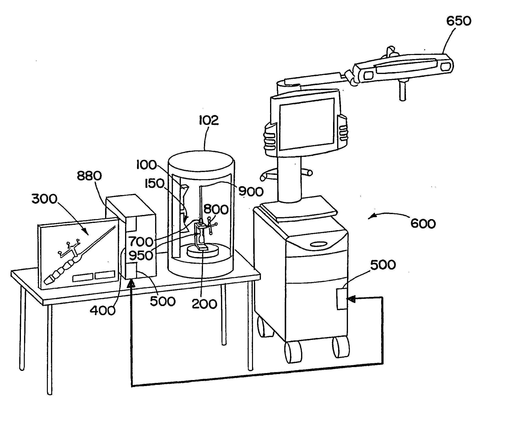
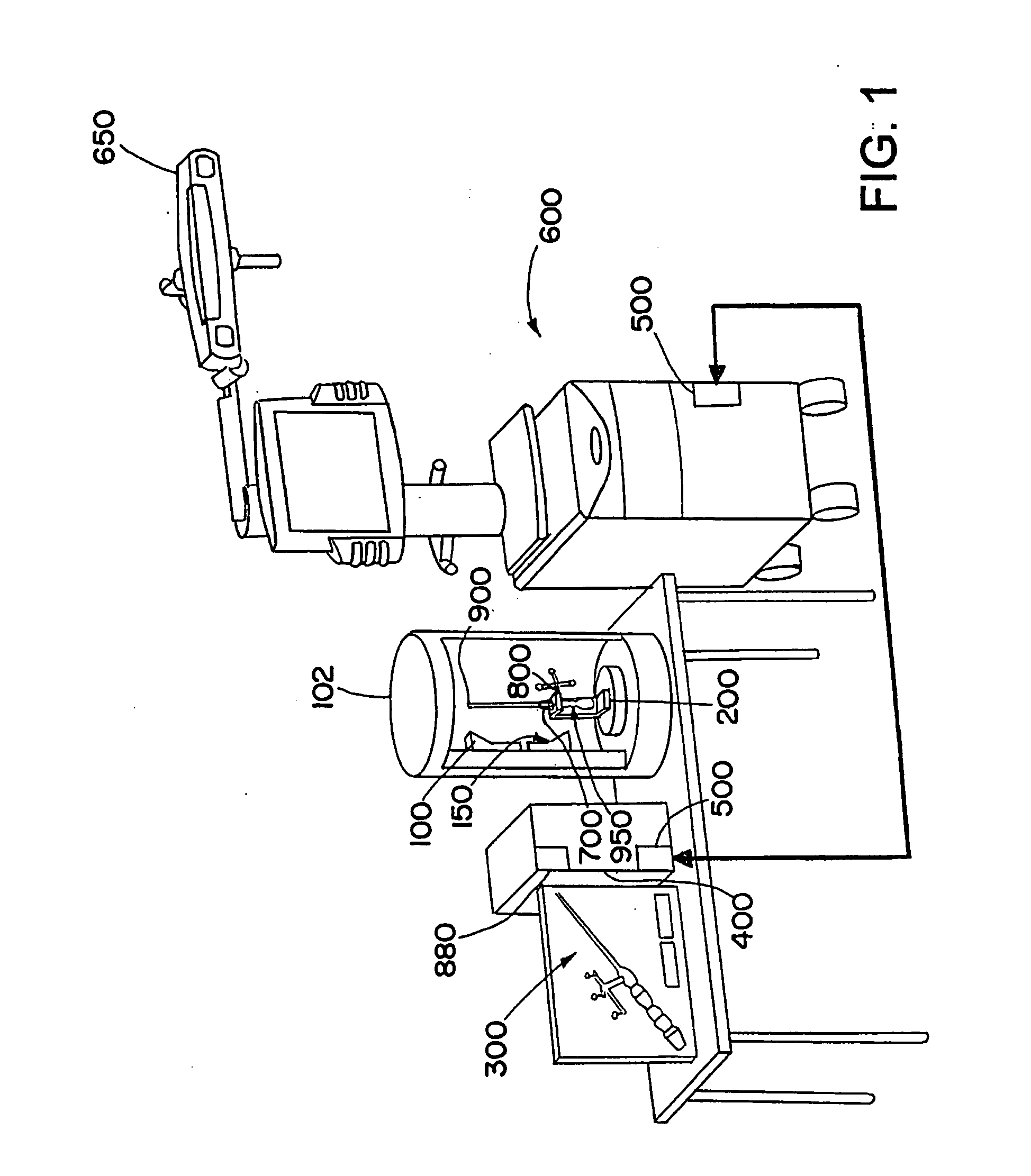
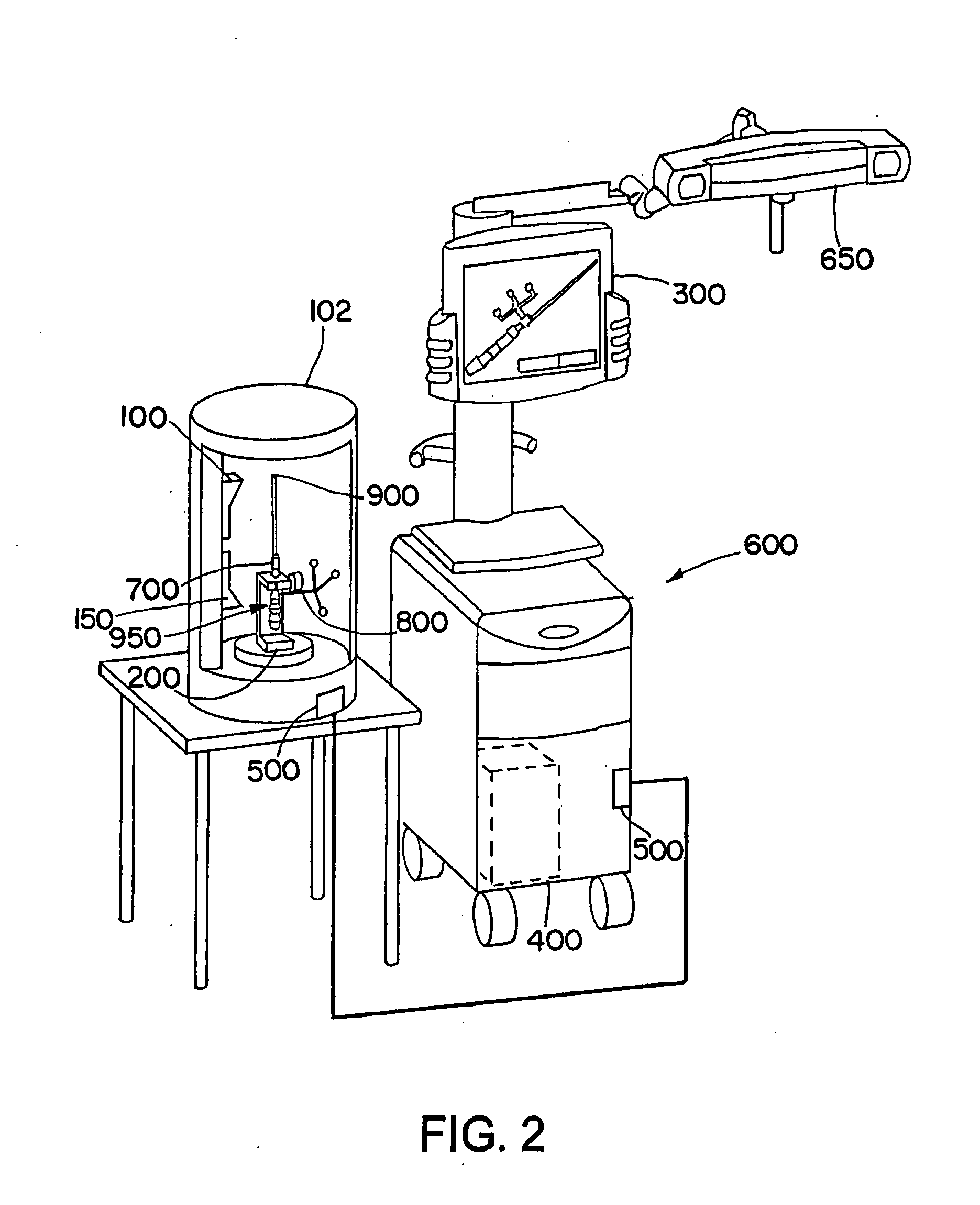
[0058]FIG. 1 illustrates an exemplary embodiment in accordance with the present invention, wherein a scanning device 100 and an instrument holding unit 200 are arranged in a cylindrical casing 102. An infrared camera unit 150 also can be attached in the casing 102 in order to check the condition, shape or quality of active or passive markers. The check can be performed, for example, by emitting infrared radiation onto the markers and, via the infrared camera unit 150, detecting the reflected infrared radiation. Alternatively, the infrared camera unit 150 can detect infrared radiation emitted by the markers. In the present example, an instrument 700 is positioned within the casing 102, preferably fixedly or non-movably in the instrument holding unit 200, wherein a reference system 800 is attached to the instrument 700 and the instrument 700 comprises an instrument tip 900 as a functional element. An RFID transponder 950 is located in the interior of the instrument 700 and / or the refe...


PUM


Abstract

A measuring device for measuring geometric properties of a medical treatment device includes a measuring unit, a time detection unit, and an RFID writer. The measuring unit is configured to measure a relative position between at least a first part of the medical treatment device and at least a second part of the medical treatment device. The time detection unit configured to detect a time of the measurement, and the RFID writer configured to write a time, based on the detected time, to an RFID transponder of the medical treatment device.

Description


Claims


Application Information

Patent Timeline
Owner BRAINLAB
Learn More