
Method for operating an internal combustion engine

a technology of internal combustion engine and operating method, which is applied in the direction of electrical control, process and machine control, instruments, etc., can solve the problems of only enabling unsatisfactory operation of internal combustion engine function, no longer able to determine current angular position, and no longer able to control internal combustion engine, etc., to improve emergency driving function and improve plausibility test

Inactive Publication Date: 2008-03-06
ROBERT BOSCH GMBH
View PDF0 Cites 42 Cited by
  • Summary
  • Abstract
  • Description
  • Claims
  • Application Information

AI Technical Summary

Benefits of technology

[0008] The object of the present invention is to enable an operation of the internal combustion engine even without the signals from a phase sensor. Furthermore, it is the object of the present invention to enable an improved emergency driving function if a disturbance of the crankshaft signal is present. Moreover, it is the object of the present invention to provide a possibility for being able to execute an improved plausibility test with respect to the determined current angular position.

Problems solved by technology

A failure of the component required for the determination of the current angular position can have the result that the current angular position can no longer be determined and the internal combustion engine can no longer be controlled.
However, the angular position of the internal combustion engine (engine position) determined using the camshaft sensor, and the rotational speed determined therewith, is often very imprecise, so that the emergency driving function enables only an unsatisfactory operation of the internal combustion engine.
However, in the case of a disturbance of the crankshaft sensor, disturbance of the phase sensor or of the camshaft sensor wheel regularly has the result that the internal combustion engine can no longer be operated.
Moreover, in known systems it can occur that it cannot be determined whether disturbance of the crankshaft sensor or of the phase sensor is present.
In this case, an emergency driving function usually also cannot be realized.
In addition, the phase sensor, the camshaft sensor wheel, the cabling, and the fastening of these components is cost-intensive, so that it would be desirable to be able to do without these components, in particular given production with high piece counts.

Method used


Image

  • Method for operating an internal combustion engine
  • Method for operating an internal combustion engine
  • Method for operating an internal combustion engine

Examples


Embodiment Construction

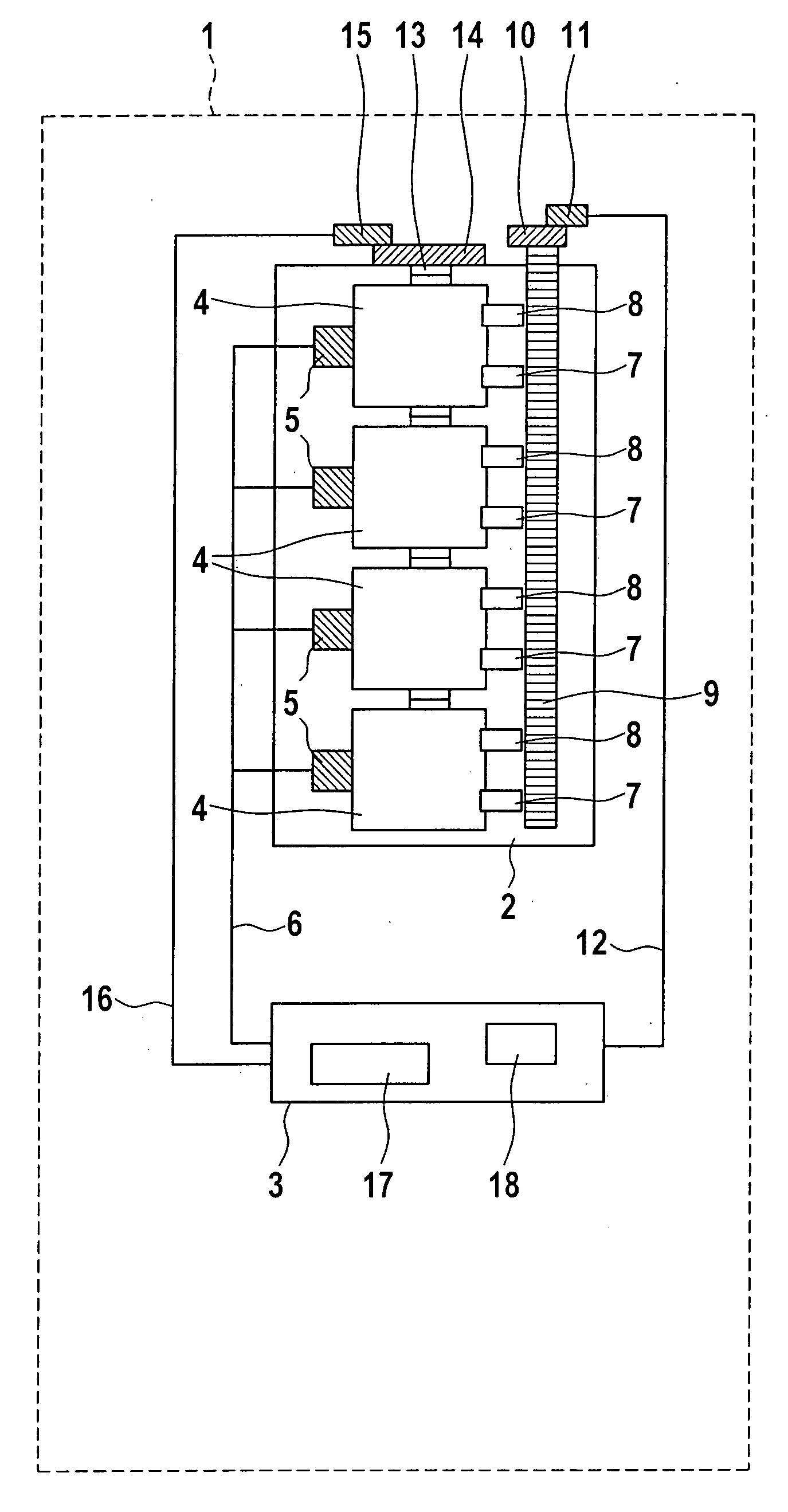
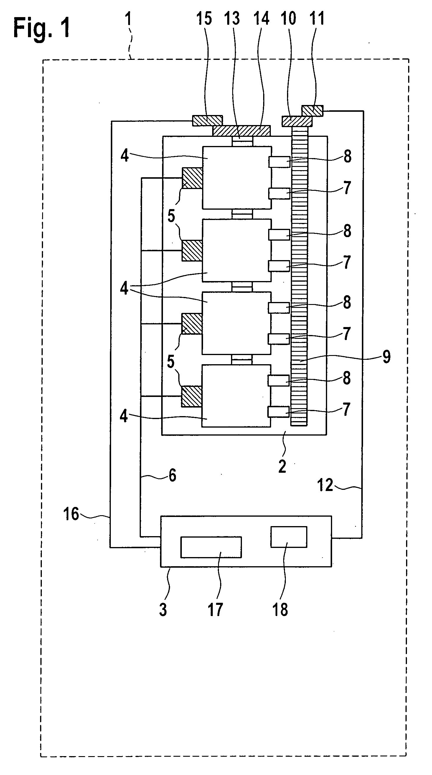
[0040]FIG. 1 shows an internal combustion engine 2 that is situated in a vehicle 1 represented by a dotted line. Internal combustion engine 2 has cylinders 4 to each of which a cylinder pressure sensor 5 is allocated in such a way that a pressure currently prevailing in the combustion chamber of cylinder 4 is capable of being acquired. Cylinder pressure sensors 5 are connected to a control device 3 via a signal line 6.

[0041] To each cylinder 4 there is allocated at least one inlet valve 7 and one outlet valve 8. Inlet valve 7 is connected to an air system (not shown) and enables the controlling of the supply of fresh air and, if necessary, residual gas, or the supply of an air-fuel mixture. Outlet valve 8 is connected to an exhaust gas system (not shown).

[0042] Inlet valves 7 and outlet valves 8 are controlled by a camshaft 9. On camshaft 9 there is situated a camshaft sensor wheel 10. A phase sensor 11 is allocated to camshaft sensor wheel 10. Camshaft sensor wheel 10 has for exa...


PUM


Abstract

To enable operation of an internal combustion engine even without the signals of a phase sensor while nonetheless enabling an emergency driving function in the case of a disturbance of a crankshaft signal acquired by a crankshaft sensor, a cylinder pressure is acquired using a cylinder pressure sensor and it is checked whether the cylinder pressure reaches a prespecifiable threshold value. When the threshold value is reached or exceeded, an angular position associated with the threshold value is inferred. The angular position is then made available for an operation of the internal combustion engine.

Description

FIELD OF THE INVENTION [0001] The present invention relates to a method for operating an internal combustion engine, the internal combustion engine having at least one cylinder, and a cylinder pressure sensor being allocated to the cylinder. The present invention also relates to an internal combustion engine having at least one cylinder, a cylinder pressure sensor being allocated to the cylinder. In addition, the present invention relates to a control device for controlling and regulating an internal combustion engine comprising at least one cylinder, a cylinder pressure sensor being allocated to the least one cylinder. Finally, the present invention relates to a computer program that is capable of being executed on a computing device, in particular on a control device for controlling and regulating an internal combustion engine. BACKGROUND INFORMATION [0002] The operation of an internal combustion engine, for example a gasoline engine or a diesel engine, requires a controlling or r...

Claims


Application Information

Patent Timeline
IPC IPC(8): F02D28/00
CPCF02D35/02F02D35/023F02D41/009F02D41/222F02D2041/227Y02T10/40
Inventor KESSLER, MICHAELBOSSMEYER, THOMASKOLBE, MICHAEL
Owner ROBERT BOSCH GMBH
Learn More