
Extension spark plug

a technology of extension and spark plugs, applied in the field of extension spark plugs, can solve the problems of complex training, logistical problems, and many problems still exis

Active Publication Date: 2008-03-06
FEDERAL MOGUL WORLD WIDE LLC
View PDF18 Cites 33 Cited by
  • Summary
  • Abstract
  • Description
  • Claims
  • Application Information

AI Technical Summary

Benefits of technology

"The present invention provides an extension-type spark plug for igniting air-fuel mixture in an internal combustion engine. The plug includes an installation conduit, contact button, electrode extension, firing electrode, ground plate, insulator sleeve, upper insulator, and lower insulator. The contact button delivers the high voltage pulse to the electrode extension, which is axially aligned with the firing electrode. The ground plate defines a spark gap with the firing electrode, and the sleeve insulator surrounds the electrode extension. The upper insulator surrounds the upper portion of the electrode extension and is in contact with the sleeve insulator, while the lower insulator surrounds the lower portion of the electrode extension and is in contact with the sleeve insulator. The contact button includes threads for engaging mating threads in the electrode extension, and the installation conduit surrounds the upper and lower insulators. The upper insulator has a cavity for receiving a first end of the sleeve insulator, while the lower insulator has a cavity for receiving a second end of the sleeve insulator. The technical effects of the invention include improved ignition performance and durability of the spark plug."

Problems solved by technology

While designs with accessory pieces meet their intended purpose, many problems still exist.
For example, spark plug designs having multiple pieces require complex training and cause logistic issues.
Further, the more complex designs require retrofit instructions.
Moreover, such designs having multiple pieces require field assembly and, thus, have a reduced reliability.

Method used


Image

  • Extension spark plug
  • Extension spark plug
  • Extension spark plug

Examples


Embodiment Construction

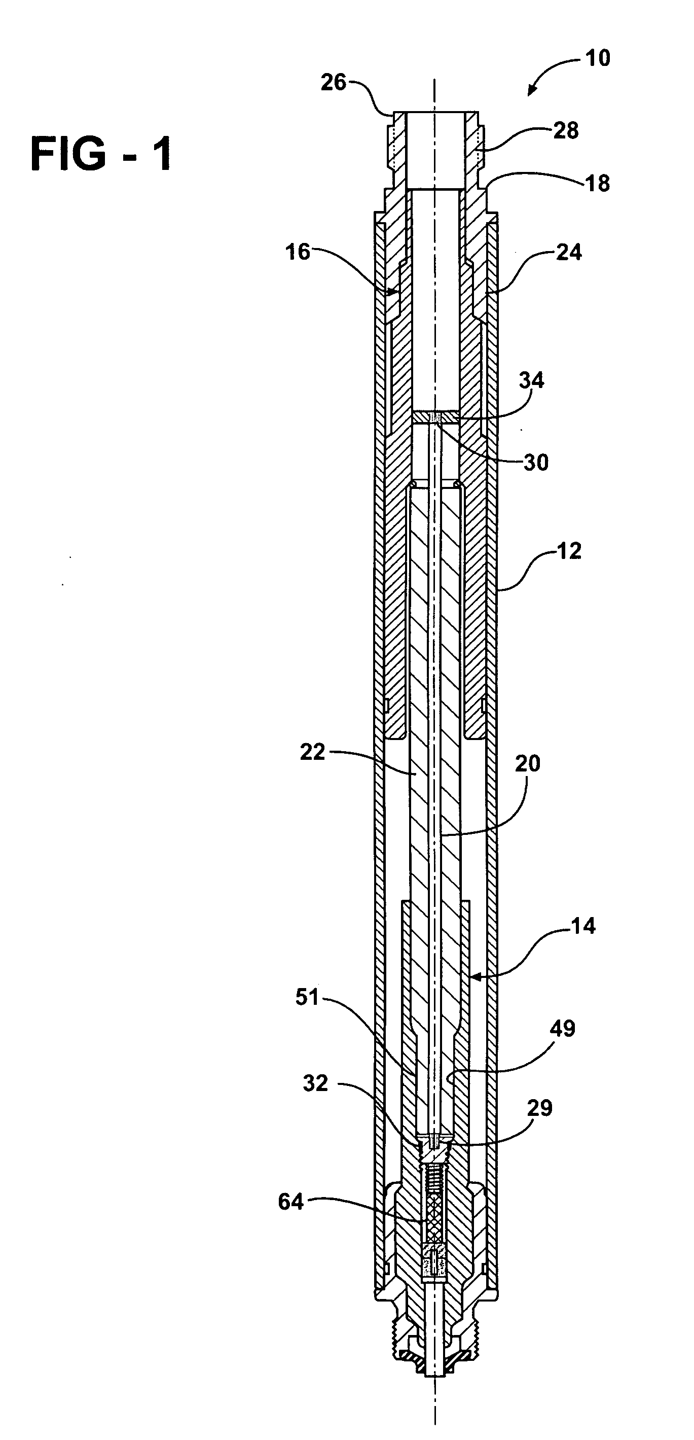
[0022]Referring now to FIG. 1, a cross-sectional view of an extension-type spark plug 10 is illustrated, in accordance with an embodiment of the present invention. The spark plug 10 is of the type used in industrial engine and other specialized applications where access to the spark plug 10 for maintenance and replacement purposes is severely limited. The spark plug 10 includes an installation conduit 12. Installation conduit 12 is made of a metal material such as stainless steel or some alloy of steel. Installation conduit 12 houses a lower assembly, generally indicated at 14, and an upper assembly, generally indicated at 16. Both the lower 14 and upper 16 assemblies are made, at least in part, from a dielectric material such as ceramic.

[0023]Lower assembly 14 and upper assembly 16 together support an electrically conductive electrode extension 20 which, in one exemplary embodiment, comprises a stiff metallic wire. In one version of the invention, the electrode extension 20 compris...


PUM


Abstract

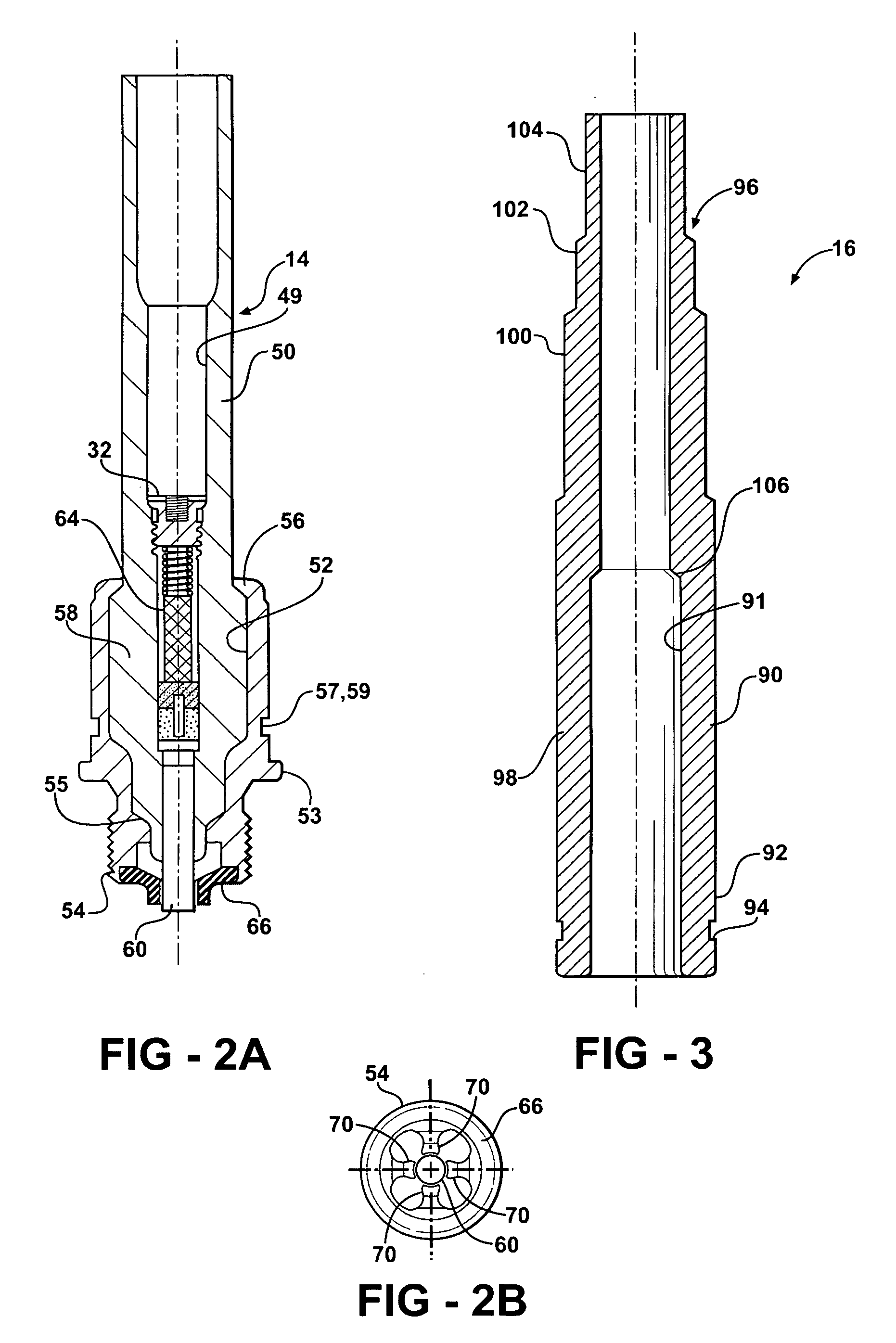
An extension-type spark plug (10) is disclosed for igniting the air-fuel mixture in an internal combustion engine. The spark plug (10) includes an installation conduit (12), a contact button (34), an electrode extension (20), a firing electrode (60), a ground plate (66), a sleeve insulator (22), an upper insulator (90) and a lower insulator (50). The electrode extension (20) is axially aligned with and in communication with the firing electrode (60). The ground plate (66) is proximate the firing electrode (60) to define a spark gap between the firing electrode (60) and a first end of the ground plate (66). The sleeve insulator (22) surrounds the electrode extension (20). The upper insulator (90) surrounds an upper portion of the electrode extension (20) and is in contact with the sleeve insulator (22). The lower insulator (50) surrounds the lower portion of the electrode extension (20) and is in contact with the sleeve insulator (22).

Description

CROSS REFERENCE TO RELATED APPLICATIONS[0001]NONE.BACKGROUND OF THE INVENTION[0002]1. Field of the Invention[0003]The present invention relates to spark plugs for igniting combustion gases in a combustion chamber of an internal combustion engine, and more particularly toward an extension type spark plug as used chiefly in specialized applications.[0004]2. Related Art[0005]Spark plugs are used in a variety of applications and are configured along with other accessory parts to fit within a given environment. For example, in a particular application the depth of the bore in the engine may require the use of a separate spark plug extension to connect the spark plug to the spark plug wire. While designs with accessory pieces meet their intended purpose, many problems still exist. For example, spark plug designs having multiple pieces require complex training and cause logistic issues. Further, the more complex designs require retrofit instructions. Moreover, such designs having multiple ...

Claims


Application Information

Patent Timeline
Patent Type & Authority Applications(United States)
IPC IPC(8): H01T13/20
CPCH01T13/20H01T13/08
Inventor CALLAHAN, RICHARD E.HIVELY, ELLEN M.
Owner FEDERAL MOGUL WORLD WIDE LLC
Learn More