
Endotracheal tube placement tool

a technology of endotracheal tube and tool, which is applied in the field of endotracheal tube placement tool, can solve the problems of difficult to consistently place the e/t tube in the trachea of the patient, difficult to insert the e/t tube in the trachea that may already be somewhat constricted, and the patient is already unconscious

Inactive Publication Date: 2008-03-06
LAUER MARK A
View PDF13 Cites 0 Cited by
  • Summary
  • Abstract
  • Description
  • Claims
  • Application Information

AI Technical Summary

Benefits of technology

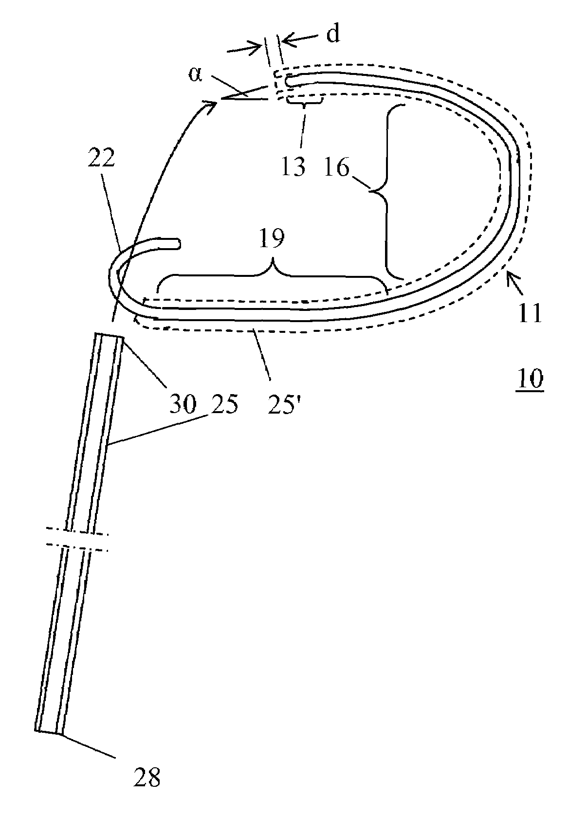
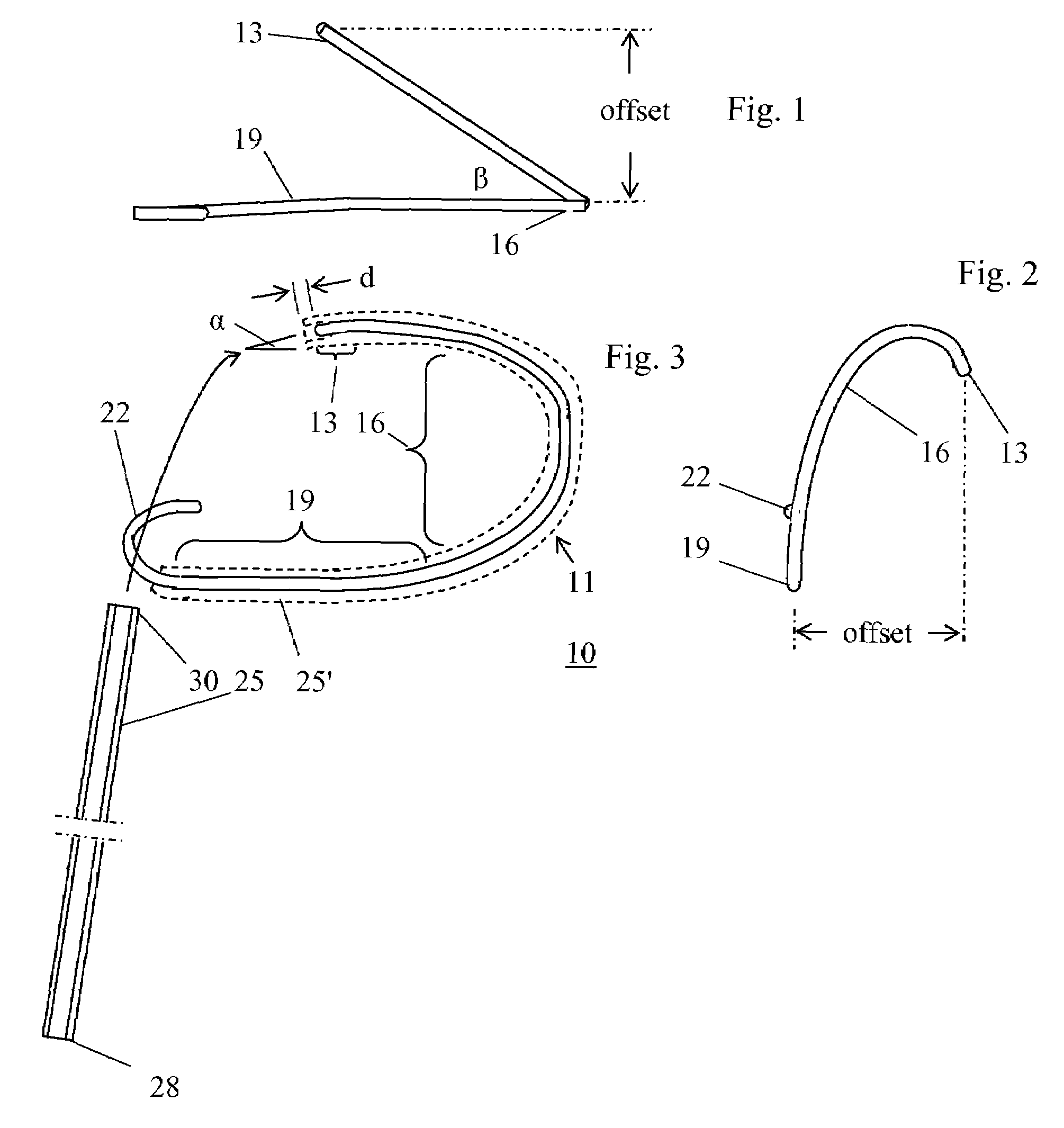
[0009]A tool in the nature of a stylet temporarily placed into the duct of an e / t tube is an effective means for assisting in rapidly and accurately inserting an e / t tube in the throat of a living being. Such a tool comprises a relatively rigid rod in a general shape referred to hereafter as an offset spiral. The tool has mandrel and handle sections that a medical professional holds during the insertion procedure. A curved arc section of the tool has a generally spiral configuration and smoothly transitions from the mandrel section. A tip section of the tool smoothly transitions from the arc section. The tip section may be curved or may also be nearly straight. The arc section angularly offsets the tip section with respect to the mandrel section. Preferably, the mandrel, arc, and tip sections are unitary, and are formed from a single piece of rod or wire.
[0011]The term “relatively rigid” means that the tool comprises a rod formed from material that is stiff enough to allow a skilled medical professional to properly place the e / t tube at the glottic opening of a patient without permanently bending the tool from the specified shape. It is convenient to form the stylet tool from heavy gauge, relatively straight, metal wire or rod by bending into the specified shape, which inherently makes the tool relatively rigid.

Problems solved by technology

When a medical professional inserts an e / t tube in a patient's trachea to provide airflow through a closed or restricted breathing passage, often the patient is already unconscious.
The e / t tube must rapidly and accurately enter the trachea during placement, since time is precious when breathing is difficult for a person.
It is difficult for a medical professional to consistently place the e / t tube in the trachea.
The flexibility of typical e / t tubes sometimes makes it difficult to insert the e / t tube in a trachea that may already be somewhat constricted.
For all of these reasons, personnel cannot always place an e / t tube in a trachea as quickly and accurately as is desirable.
The professional can usually detect improper e / t tube placement, but the delay is undesirable.
E / b scopes cost thousands of dollars, and hence are not disposable devices.
Therefore, they require sterilization between uses, which may some times be inconvenient.

Method used


Image

  • Endotracheal tube placement tool
  • Endotracheal tube placement tool

Examples


Embodiment Construction

[0016]FIGS. 1, 2, and 3 collectively show an e / t tube placement tool 10 in the form of a stylet for inserting an e / t tube 25 in a patient's trachea. FIGS. 1-3 are aligned as orthographic projections of the top, end, and side of tool 10. FIG. 3 shows e / t tube 25 in phantom at 25′ mounted on tool 10 to form a tool assembly 11 that is prepared for use by a medical professional to insert e / t tube 25 in a patient's trachea. For simplicity, tube 25 is omitted from FIGS. 1 and 2. For the same reason, the balloon and attachment fitting mentioned in the Background section are omitted from e / t tube 25. E / t tube 25 has leading and trailing ends 28 and 30 respectively.

[0017]Principles of descriptive geometry teach that three orthographic projections are sufficient to completely describe the shape of a simple curved line. Tool 10 may be represented as a simple curved line. Hence, the orthographic projections of FIGS. 1-3 are sufficient to define the shape of tool 10 in a manner allowing one with...


PUM


Abstract

A tool for assisting a medical professional in inserting an endotracheal tube in the trachea of a patient comprises a relatively rigid rod in the shape of an offset spiral. The tool has a mandrel section, a curved arc section smoothly transitioning from the mandrel section, and a tip section smoothly transitioning from the arc section. The arc section is an arc of a three dimensional spiral, and angularly and spatially offsets the tip section with respect to the mandrel section.

Description

BACKGROUND OF THE INVENTION[0001]An endotracheal (e / t) tube is a medical device in the form of a tube that is inserted to extend through a patient's glottic opening and into the trachea to assist breathing. An e / t tube for an adult patient typically comprises a soft, pliable plastic hose, perhaps 10-11.5 mm. OD and 6.5-8.0 mm. ID with a uniform cross section, and with a length typically ranging from 30-35 cm. A pediatric e / t tube may be approximately two-thirds the length and OD of an adult e / t tube. An infant e / t tube may be one-half the size of an adult e / t tube. E / t tubes must be pliable so that they can conform to the shape of the patient's throat, and so they can bend within the mouth to protrude from the patient's lips.[0002]An e / t tube has a leading end that a medical professional inserts in the patient's throat and pushes into the trachea to a distance of 2-4 cm. The length of the e / t tube allows a trailing end of an inserted e / t tube to project from the patient's mouth.[000...

Claims


Application Information

Patent Timeline
IPC IPC(8): A61B17/00A62B9/06A61M16/00
CPCA61M16/0488
Inventor LAUER, MARK A.
Owner LAUER MARK A
Learn More