
Multi-Frequency Fire Alarm Sounder

a multi-frequency, sounder technology, applied in mechanical vibration separation, hydraulic/pneumatic audible signalling, signalling system, etc., can solve the problems of unacceptably low sound intensity in a complex set of zones, and the possibility of not being able to clearly hear the alarm

Active Publication Date: 2008-02-28
HONEYWELL INT INC
View PDF12 Cites 2 Cited by
  • Summary
  • Abstract
  • Description
  • Claims
  • Application Information

AI Technical Summary

Benefits of technology

The system effectively eliminates low sound intensity zones and enhances sound penetration through doors and walls, while optimizing power usage by varying frequencies and duty cycles, ensuring clear alarm notification across a region with reduced power requirements.

Problems solved by technology

In an indoor environment, single frequency driving of the horn or transducer can produce a complex set of zones of unacceptably low sound intensity.
The presence of unacceptably low sound intensity zones results in a circumstance where an alarm might not be clearly heard by a person who happened to be in any such zone.

Method used


Image

  • Multi-Frequency Fire Alarm Sounder
  • Multi-Frequency Fire Alarm Sounder
  • Multi-Frequency Fire Alarm Sounder

Examples


Embodiment Construction

[0012] While embodiments of this invention can take many different forms, specific embodiments thereof are shown in the drawings and will be described herein in detail with the understanding that the present disclosure is to be considered as an exemplification of the principles of the invention and is not intended to limit the invention to the specific embodiment illustrated.

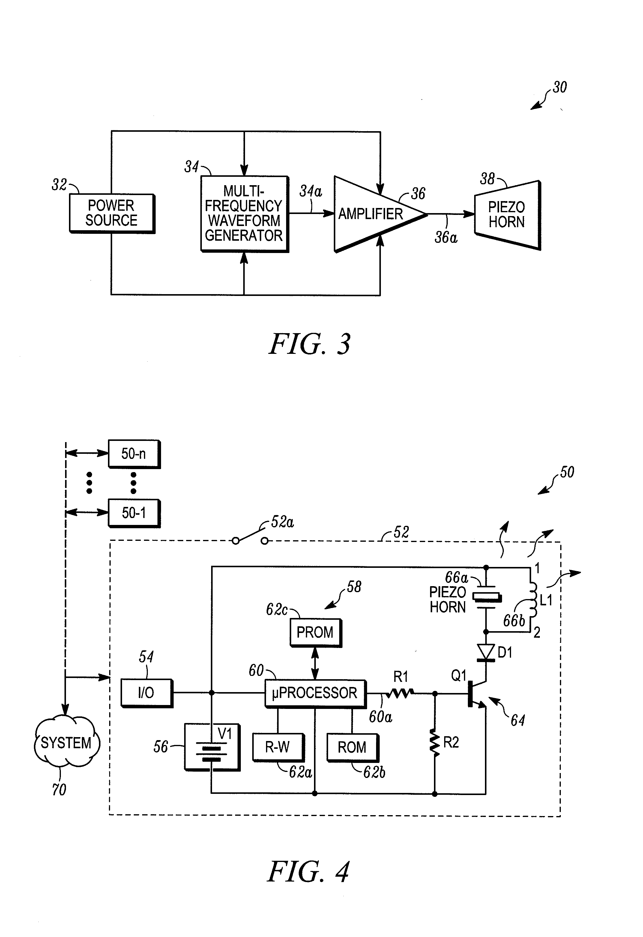
[0013] An audible output device which embodies the invention incorporates a rapidly changing set of frequencies to drive an audible output transducer. Since each frequency produces a different set of standing waves within the immediate vicinity of the device, rapidly varying the frequencies also rapidly changes the locations of the standing waves, hence, also changing the location of zones of low sound intensity.

[0014] As a result of repetitively changing the locations of relatively low sound intensity in a region or a room, it is highly unlikely that a person in the region or room would be in a zone which exh...


PUM


Abstract

An audible output device, of a type usable in a fire alarm system, incorporates a multi-frequency waveform generator. The generator produces a plurality of frequencies with predetermined duty factors during various time intervals on a repetitive basis. The multi-frequency drive signal is in turn coupled to an audible output device such as a piezoelectric horn or the like. The multi- frequency audio output provides an indicator to persons adjacent to the device of the presence of an alarm condition.

Description

CROSS-REFERENCE TO RELATED APPLICATIONS [0001] The present application is a Continuation of and claims the benefit of the filing date of U.S. Utility Application No. 11 / 008,595 filed on Dec. 9, 2004 entitled “Multi-Frequency Fire Alarm Sounder,” which is incorporated herein by reference.FIELD OF THE INVENTION [0002] The invention pertains to fire alarm indicating devices which emit audible outputs. More particularly, the invention pertains to such devices, such as horns or the like, which might be driven by multi-frequency input signals. BACKGROUND OF THE INVENTION [0003] It has been known in the prior art to drive a horn or other form of audible output transducer at a single frequency to indicate an alarm condition. In an indoor environment, single frequency driving of the horn or transducer can produce a complex set of zones of unacceptably low sound intensity. These are thought to arise from standing waves caused by the sound waves reflecting from surfaces, such as room surfaces,...

Claims


Application Information

Patent Timeline
Patent Type & Authority Applications(United States)
IPC IPC(8): G08B3/00
CPCB06B1/0284
Inventor KEELER, MANLEY S.FISLER, CHARLES F.HA, SIMON
Owner HONEYWELL INT INC
Learn More