
Device for measuring depth for use with dial height gauge

Inactive Publication Date: 2008-02-28
LEE BONG
View PDF9 Cites 16 Cited by
  • Summary
  • Abstract
  • Description
  • Claims
  • Application Information

AI Technical Summary

Benefits of technology

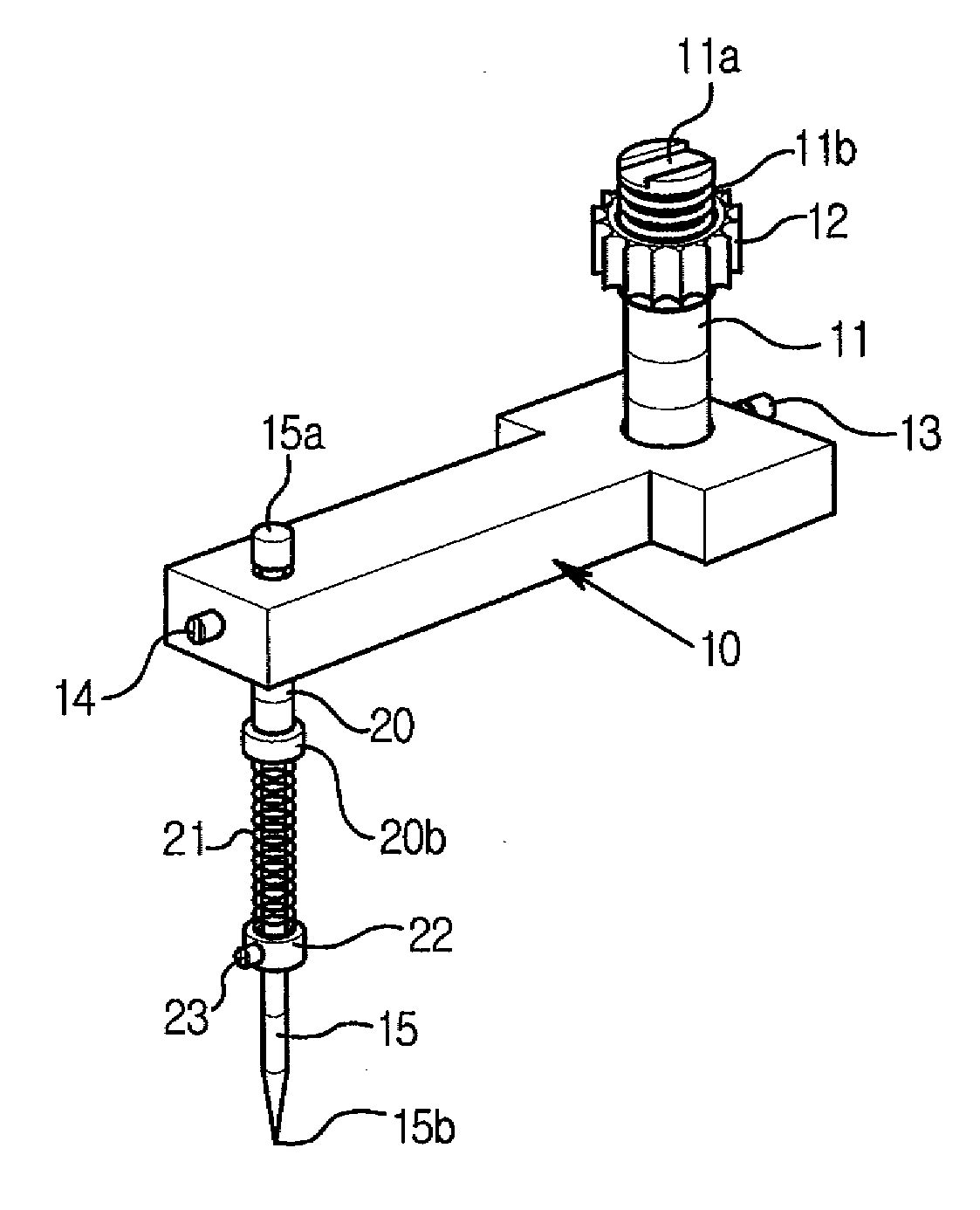
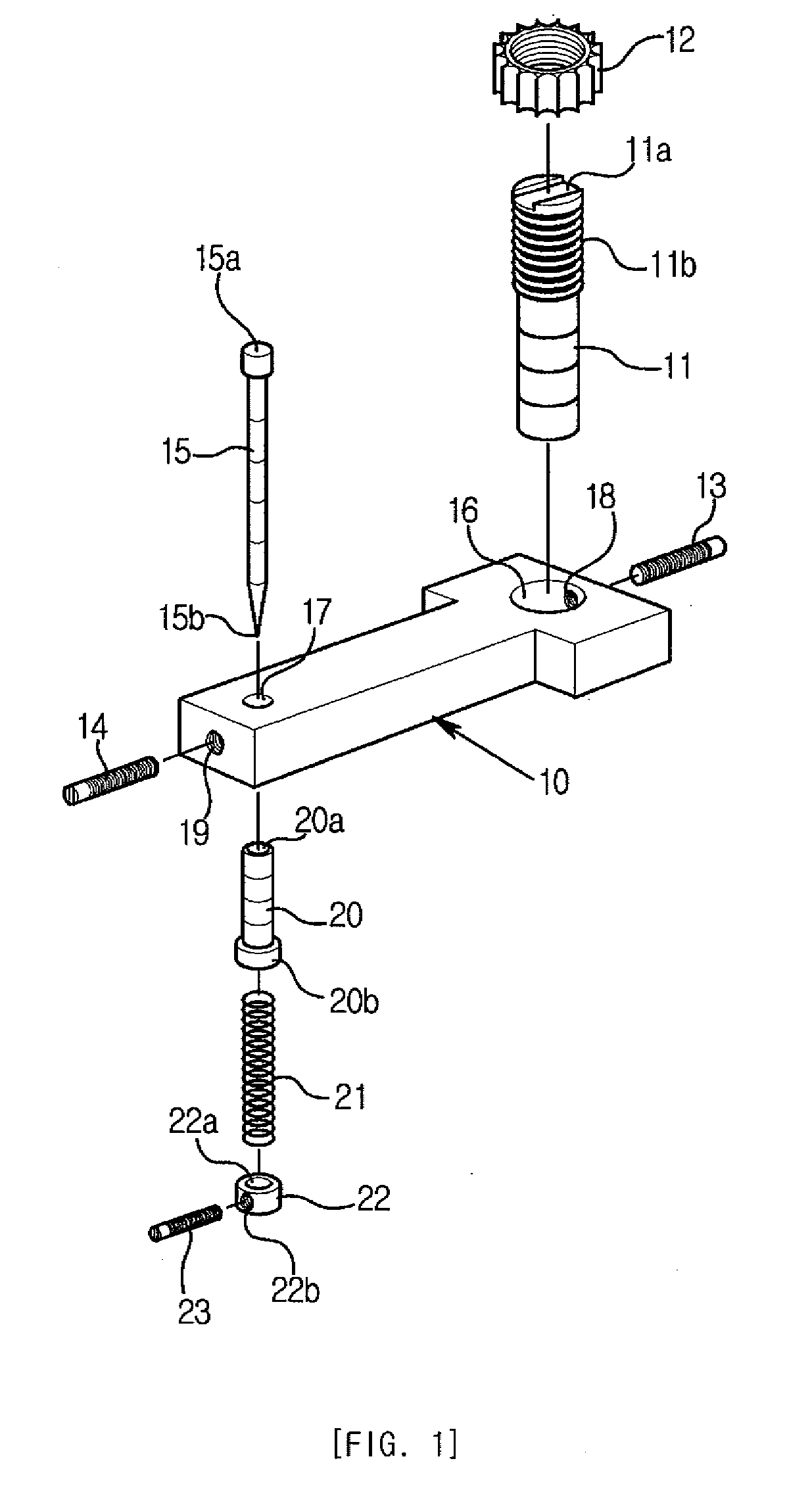
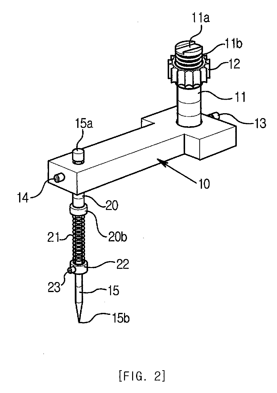
[0011]Here, the touch pin reciprocates in the hollow cylindrical column fixed to the main body. The spring plays a role of making the touch pin touch an object to be measured on a spring sensitive touch basis. The touch pin is fitted through the coiled spring. The touch pin is fixed by the third screw bolt fitted into the third fixing screw hole formed on the compression ring. The upper head of the touch pin makes the touch pin supported by the hollow cylindrical column to thus prevent the touch pin from seceding into the hollow cylindrical column. The lower head of the hollow cylindrical column makes the spring compressed against the compression ring, to thus prevent the spring from being pushed up and thus make the spring compressed between the lower head of the hollow cylindrical column and the compression ring. The lower end of the touch pin is formed like an auger so as to measure a narrow groove.

Problems solved by technology

A conventional auxiliary device for measuring depth of a groove is a pair of dial or digital calipers (namely, a pair of vernier calipers) for measuring depth but is not effective to measure an elongate deep groove or hole.
However, the three-dimensional measuring instrument or the desktop depth dial measuring instrument is not so easy to move.
As a result, since a pair of vernier calipers are inexpensive and convenient to be used and easy to movably measure a desired physical quantity, they cannot help being used on a manufacturing site.
Therefore, depth is measured with a pair of vernier calipers but a measurement error is so big.
Thus, the vernier calipers are improper to measure small-size accurate parts or molds.

Method used


Image

  • Device for measuring depth for use with dial height gauge
  • Device for measuring depth for use with dial height gauge
  • Device for measuring depth for use with dial height gauge

Examples


Embodiment Construction

[0016]The structure and function of a device for measuring depth for use with a dial height gauge according to the present invention will be described in detail below with reference to the accompanying drawings.

[0017]The whole structure of a device for measuring depth for use with a dial height gauge, according to the present invention is shown in FIG. 1. In FIG. 2, the device for measuring depth for use with a dial height gauge, according to the present invention is assembled. The state where the whole structure of a device for measuring depth is installed in a dial height gauge, according to the present invention is shown in FIG. 3.

[0018]As illustrated in FIGS. 1 to 3, a device for measuring depth of an elongate deep groove or hole in a small-size mold can be used with a dial height gauge. The depth measuring device can be installed in the dial height gauge.

[0019]The depth measuring device includes a fixing portion formed of a cylindrical column 11 on the upper portion of which th...


PUM


Abstract

Provided is a device for measuring depth of an elongate deep groove or hole in a small-size mold for use with a dial height gauge. The depth measuring device includes: a fixing portion; an upper head type touch pin; and a hammer-shaped main body having a first vertical hole through which the fixing portion is fitted and a second vertical hole through which the touch pin and the hollow cylindrical column are fitted. The depth measuring device can be conveniently assembled and disassembled, to thus enable a user to easily replace a damaged touch pin with a new one. Touch pins of various size that are fit for depth and width of grooves can be purchased at low cost. The depth measuring device enables a user to measure a desired physical quantity up to a 0.01 mm error range in accuracy as well as greatly contribute for a precision industry development. The depth measuring device provides an effect of greatly reducing labor power and cost for manufacturing molds.

Description

CROSS-REFERENCE TO RELATED PATENT APPLICATION[0001]This application claims the benefit of Korean Utility-model Application No. 20-2006-0022407, filed on Aug. 22, 2006, in the Korean Intellectual Property Office, the disclosure of which is incorporated herein in its entirety by reference.BACKGROUND OF THE INVENTION[0002]1. Field of the Invention[0003]The present invention relates to a device for measuring depth of an elongate groove of a precise and compact up-to-date component for use with a dial height gauge, and more particularly, to a device measuring depth for use with a dial height gauge, in which an elongate pin combined with a spring is installed on a dial height gauge so as to be conveniently used.[0004]2. Description of the Related Art[0005]A conventional auxiliary device for measuring depth of a groove is a pair of dial or digital calipers (namely, a pair of vernier calipers) for measuring depth but is not effective to measure an elongate deep groove or hole. Accordingly, ...

Claims


Application Information

Patent Timeline
IPC IPC(8): G01B3/28
CPCG01B3/28G01B5/02G01B5/00
Inventor LEE, BONG-AE
Owner LEE BONG
Learn More