
Anterior cervical spine instrumentation and related surgical method

an instrumentation and cervical spine technology, applied in the field of anterior cervical spine instrumentation, can solve the problems that no conventional surgical instrument for cervical spine fusion is known in the art, and achieve the effect of preventing the expulsion of the retractor devi

Inactive Publication Date: 2008-02-21
US SPINE INC
View PDF18 Cites 57 Cited by
  • Summary
  • Abstract
  • Description
  • Claims
  • Application Information

AI Technical Summary

Benefits of technology

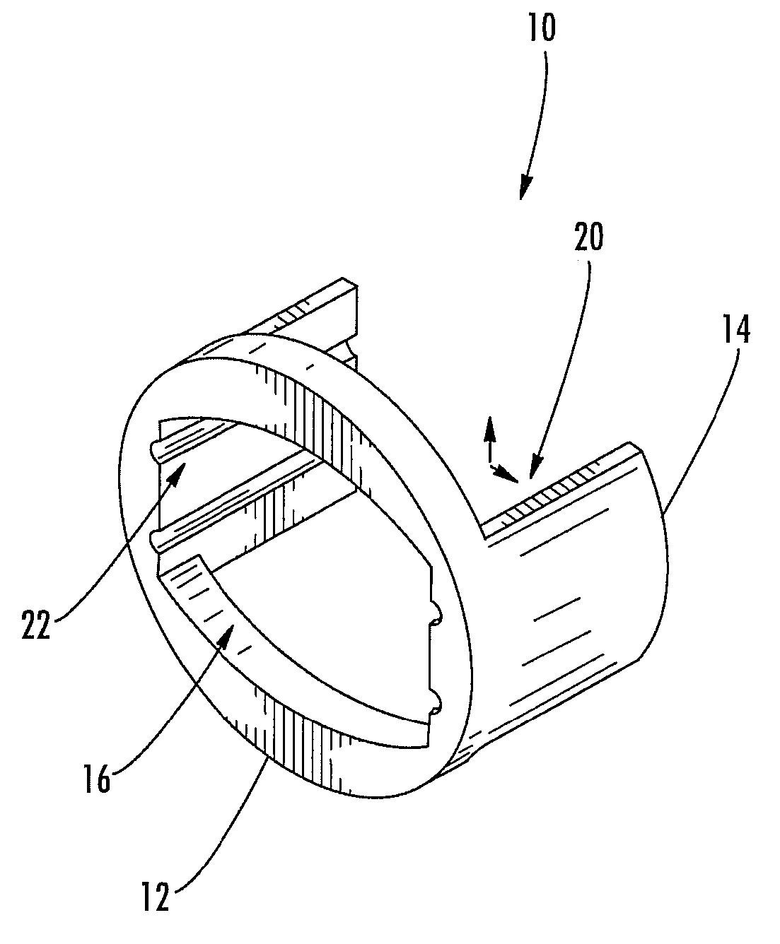
[0005] In various exemplary embodiments, the present invention provides a set of less invasive cervical spine instruments that are used to achieve cervical disc decompression, bone preparation, and the alignment of one or more matched sized bone grafts prior to cervical plate placement. This set of less invasive cervical spine instruments, and the related surgical method, result in reduced surgical time, the preparation of a precise machined bone surface while simultaneously maintaining the cervical disc decompression height of the intervertebral endplates, the selection of one or more prefabricated bone dowel grafts sized to match the machined bone surface and maximizing the surface contact required for cervical spine fusion, the placement of the one or more prefabricated bone dowel grafts (e.g. side by side) that can be of different diameters in order to fully exploit the intervertebral space available, and the alignment of the cervical plate using a cervical spine instrument that is matched to align with the one or more prefabricated bone dowel grafts beneath the cervical plate.
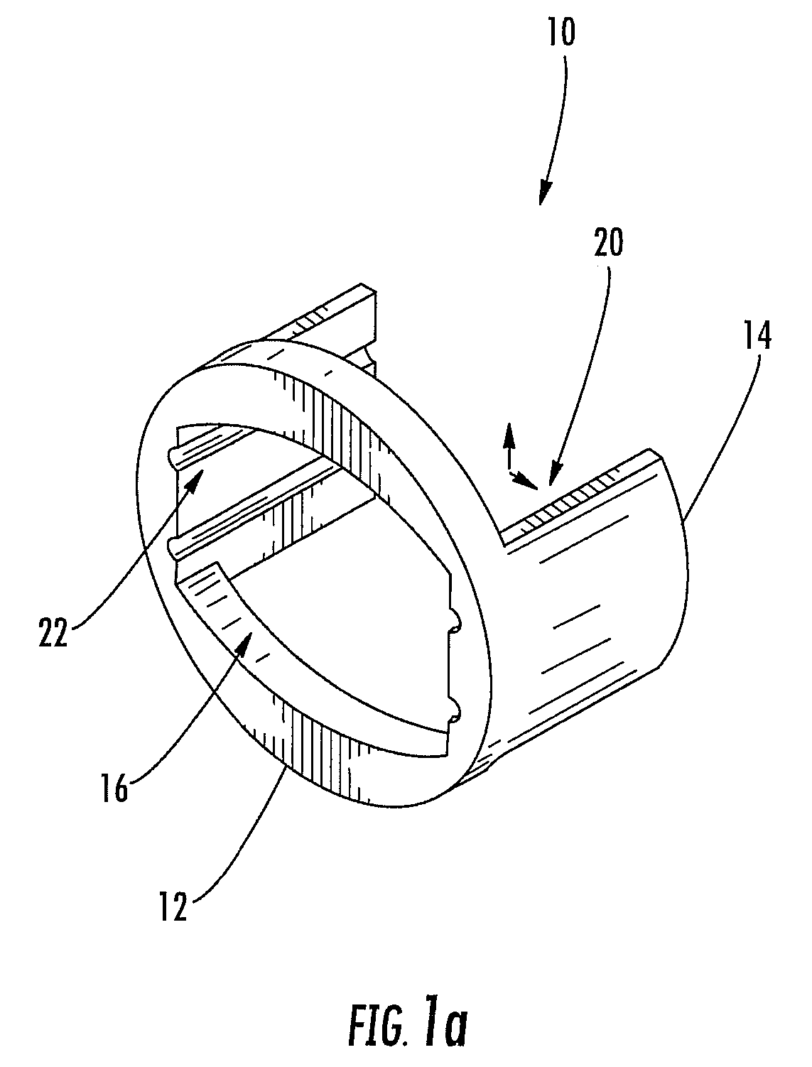
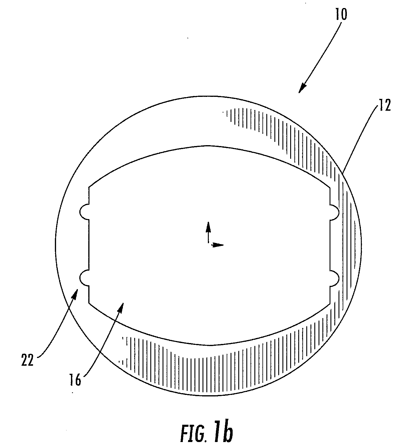
[0008] In another exemplary embodiment, the present invention provides a surgical method for achieving cervical disc decompression, bone preparation, and the alignment of one or more matched sized bone grafts prior to cervical plate placement, the surgical method including: placing a smaller retractor device between adjacent intervertebral enplates of the spine of a patient, the smaller retractor device including a front member defining an opening and a pair of opposed wing members each having structured top and bottom edges for engaging bone and preventing expulsion of the retractor device, wherein each of the pair of opposed wing members includes one or more guide channels; disposing one or more successively larger dilator devices through the opening defined by the front member of the retractor device and into the intervertebral space between the adjacent intervertebral endplates; wherein each of the one or more dilator devices includes one or more guide protrusions configured to engage the one or more guide channels of the pair of opposed wing members of the smaller retractor device; and placing a larger retractor device between the adjacent intervertebral enplates of the spine of the patient, the larger retractor device including a front member defining an opening and a pair of opposed wing members each having structured top and bottom edges for engaging bone and preventing expulsion of the retractor device, wherein each of the pair of opposed wing members includes one or more guide channels. Each of the one or more successively larger dilator devices also includes a shoulder stop configured to engage the front member of the smaller retractor device. The surgical method also includes disposing a portion of a drill guide defining one or more substantially circular internal channels that are each configured to receive a drill bit through the opening defined by the front member of the larger retractor device, wherein the drill guide includes one or more guide protrusions configured to engage the one or more guide channels of the pair of opposed wing members of the larger retractor device. The drill guide also includes a shoulder stop configured to engage the front member of the larger retractor device. The one or more substantially circular internal channels of the drill guide are arranged in one of a single-channel configuration, a dual-channel configuration, and a dual overlapping-channel configuration. The surgical method further includes disposing one or more bone graft dowel pins through the opening defined by the front member of the retractor device, wherein each of the one or more bone graft dowel pins includes a reference hole at its end. The surgical method still further includes disposing a cervical plate over the one or more done graft dowel pins once they are placed, wherein the cervical plate includes one or more screw holes disposed therethrough and one or more holes or slots disposed therethrough for receiving one or more alignment pins that are each configured to engage the reference hole of each of the one or more bone graft dowel pins.

Problems solved by technology

No conventional surgical instruments for cervical spine fusion are known in the art, however, that use a retractor in combination with a drill guide as part of an integrated method for bone graft selection and placement.

Method used


Image

  • Anterior cervical spine instrumentation and related surgical method
  • Anterior cervical spine instrumentation and related surgical method
  • Anterior cervical spine instrumentation and related surgical method

Examples


Embodiment Construction

[0024] In various exemplary embodiments, the present invention provides a set of less invasive cervical spine instruments that are used to achieve cervical disc decompression, bone preparation, and the alignment of one or more matched sized bone grafts prior to cervical plate placement. This set of less invasive cervical spine instruments, and the related surgical method, result in reduced surgical time, the preparation of a precise machined bone surface while simultaneously maintaining the cervical disc decompression height of the intervertebral endplates, the selection of one or more prefabricated bone dowel grafts sized to match the machined bone surface and maximizing the surface contact required for cervical spine fusion, the placement of the one or more prefabricated bone dowel grafts (e.g. side by side) that can be of different diameters in order to fully exploit the intervertebral space available, and the alignment of the cervical plate using a cervical spine instrument that...


PUM


Abstract

In various exemplary embodiments, the present invention provides a set of less invasive cervical spine instruments that are used to achieve cervical disc decompression, bone preparation, and the alignment of one or more matched sized bone grafts prior to cervical plate placement. This set of less invasive cervical spine instruments, and the related surgical method, result in reduced surgical time, the preparation of a precise machined bone surface while simultaneously maintaining the cervical disc decompression height of the intervertebral endplates, the selection of one or more prefabricated bone dowel grafts sized to match the machined bone surface and maximizing the surface contact required for cervical spine fusion, the placement of the one or more prefabricated bone dowel grafts (e.g. side by side) that can be of different diameters in order to fully exploit the intervertebral space available, and the alignment of the cervical plate using a cervical spine instrument that is matched to align with the one or more prefabricated bone dowel grafts beneath the cervical plate.

Description

CROSS-REFERENCE TO RELATED APPLICATION(S) [0001] The present non-provisional patent application claims the benefit of priority of U.S. Provisional Patent Application No. 60 / 839,095 (John SLEDGE), filed on Aug. 21, 2006, and entitled “ANTERIOR CERVICAL SPINE INSTRUMENTATION AND RELATED SURGICAL METHOD,” the contents of which are incorporated in full by reference herein.FIELD OF THE INVENTION [0002] The present invention relates generally to anterior cervical spine instrumentation and a related surgical method for aligning a cervical plate over an intervertebral bone graft. More specifically, the present invention relates to a set of less invasive cervical spine instruments that can be used to achieve cervical disc decompression, bone preparation, and the alignment of one or more matched sized bone grafts prior to cervical plate placement. BACKGROUND OF THE INVENTION [0003] A large portion of conventional surgical methods for cervical spine fusion is dedicated to performing cervical d...

Claims


Application Information

Patent Timeline
IPC IPC(8): A61F2/44A61B17/58
CPCA61B17/1757A61B2017/0256A61B17/7059
Inventor SLEDGE, JOHN
Owner US SPINE INC
Learn More