Protective Device For A Lamp
a technology for protecting devices and lamps, applied in the direction of protective devices for lighting, packaging types, special packaging, etc., can solve the problems of people being injured, excess pressure produced cannot escape the protective envelope, and may occur dangerous states described in more detail below
- Summary
- Abstract
- Description
- Claims
- Application Information
AI Technical Summary
Benefits of technology
Problems solved by technology
Method used
Image

Examples
Embodiment Construction
[0005] The invention is based on the object of providing a protective device for a lamp in which improved protection against splinters at the same time as optimized protection of the lamp against breakage is made possible in comparison with conventional solutions.
[0006] This object is achieved as regards the protective device for a lamp by the features of claim 1. Particularly advantageous embodiments of the invention are described in the dependent claims.
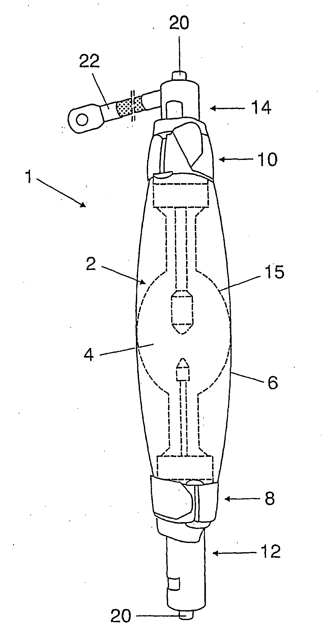
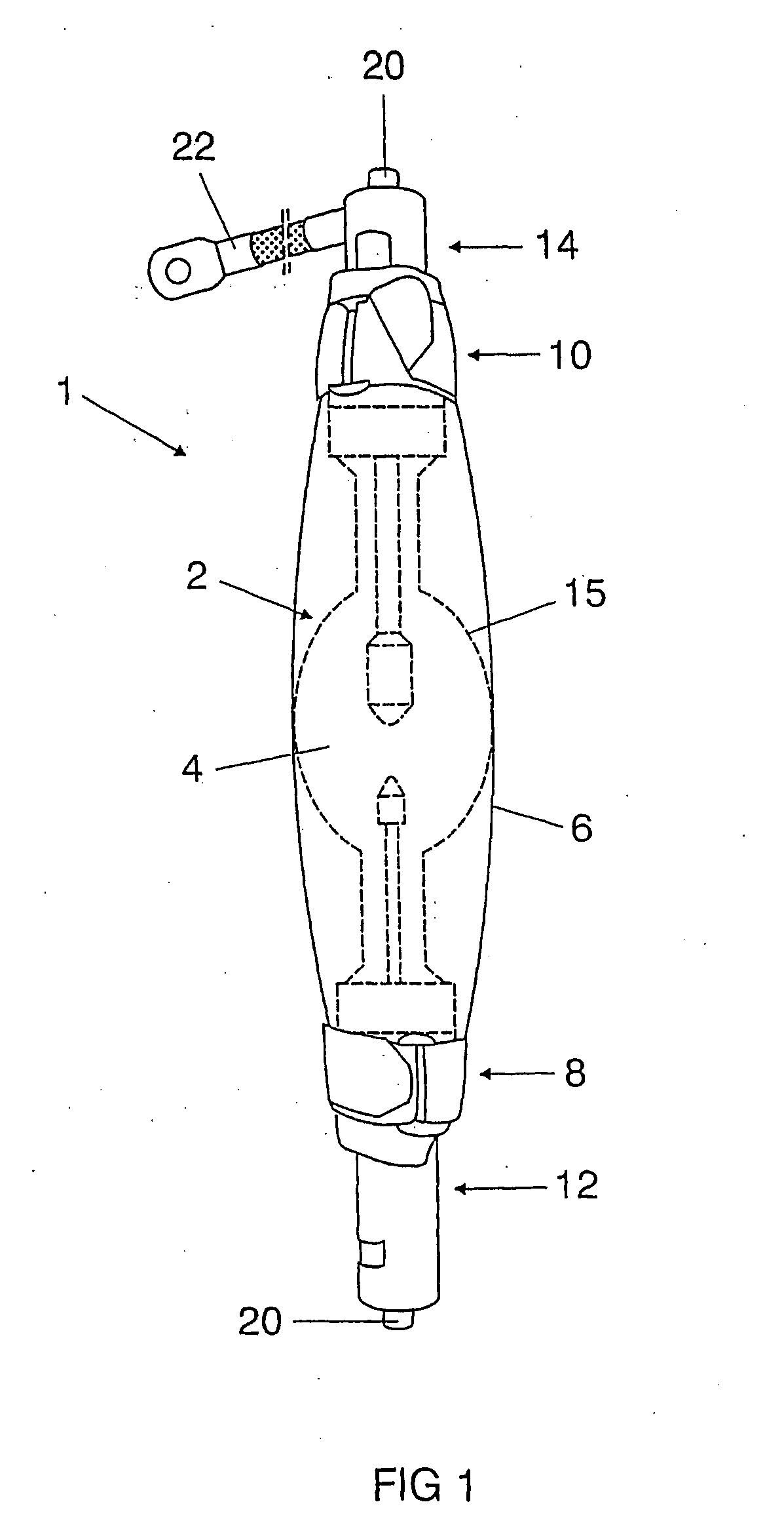
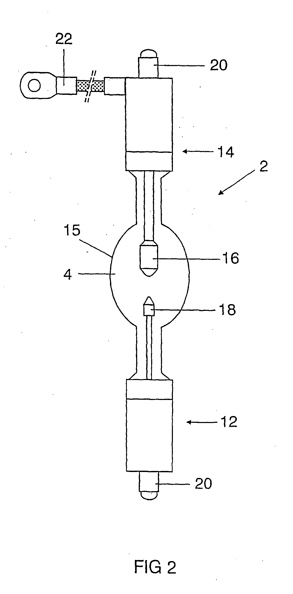
[0007] The protective device according to the invention for a lamp, in particular for a high-pressure xenon or mercury discharge lamp, having a pressurized lamp vessel uses a protective envelope, which surrounds at least sections of the lamp and can be fixed to the lamp by means of two closures engaging around bases of the lamp. According to the invention, the protective envelope consists of a gas-permeable nonwoven material, which prevents a pressure buildup within the protective envelope in the event of the lamp bursting and, a...
PUM
 Abstract
Description
Claims
Application Information
 - R&D
- Intellectual Property
- Life Sciences
- Materials
- Tech Scout
- Unparalleled Data Quality
- Higher Quality Content
- 60% Fewer Hallucinations
Browse by: Latest US Patents, China's latest patents, Technical Efficacy Thesaurus, Application Domain, Technology Topic, Popular Technical Reports.
© 2025 PatSnap. All rights reserved.Legal|Privacy policy|Modern Slavery Act Transparency Statement|Sitemap|About US| Contact US: help@patsnap.com