Fuel injection system with cross-flow nozzle for enhanced compressed natural gas jet spray
- Summary
- Abstract
- Description
- Claims
- Application Information
AI Technical Summary
Benefits of technology
Problems solved by technology
Method used
Image
Examples
Embodiment Construction
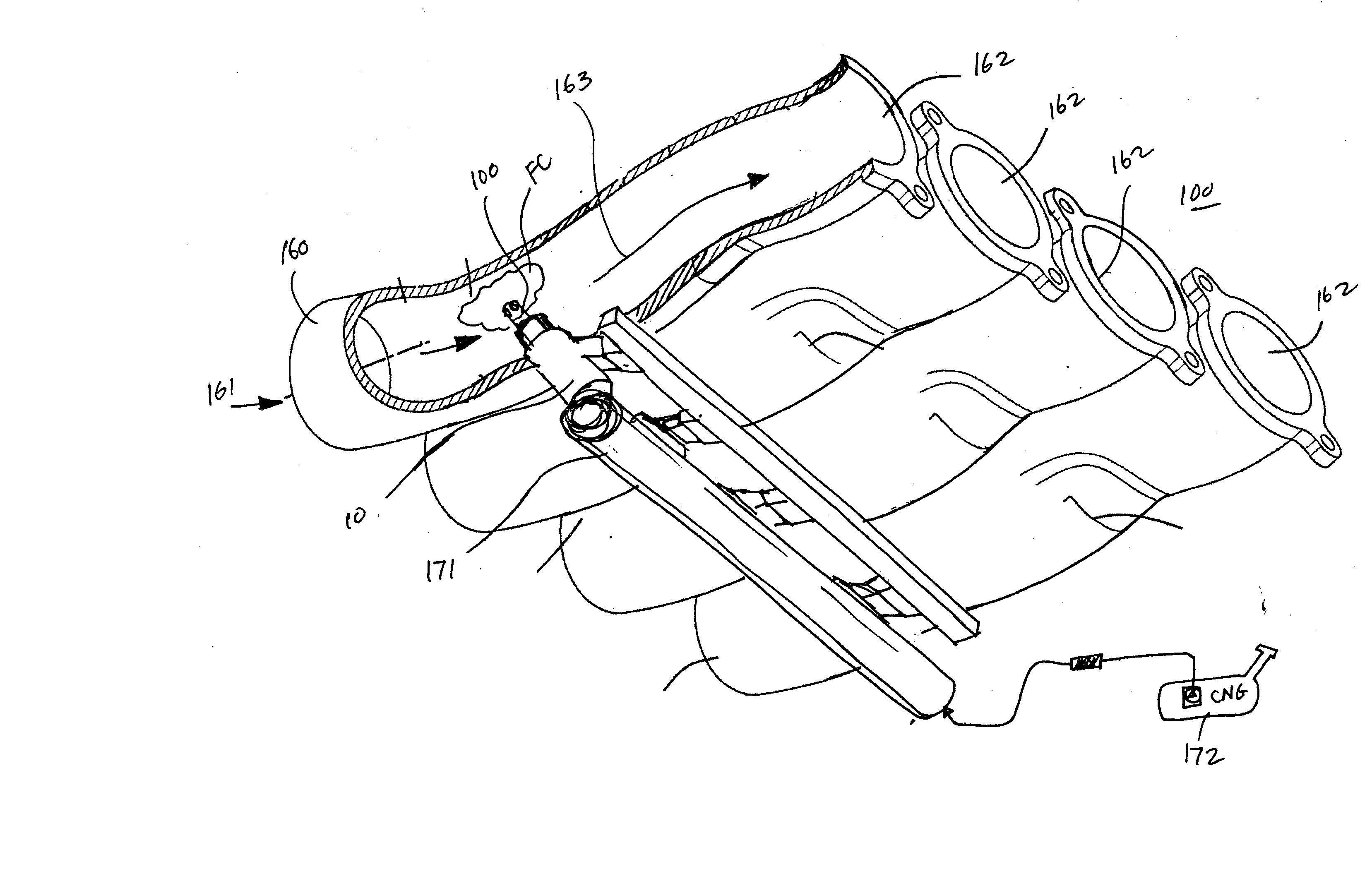
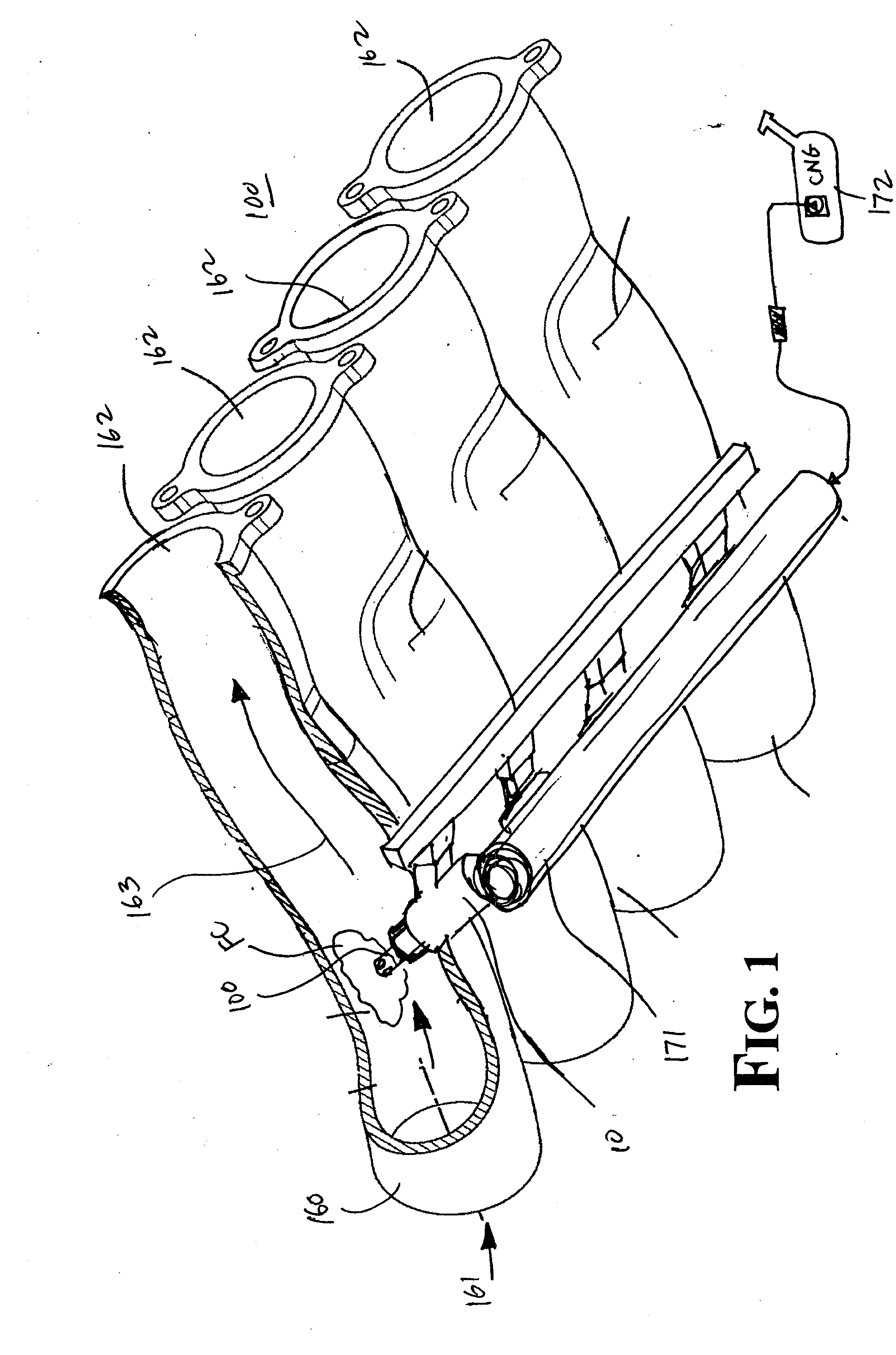
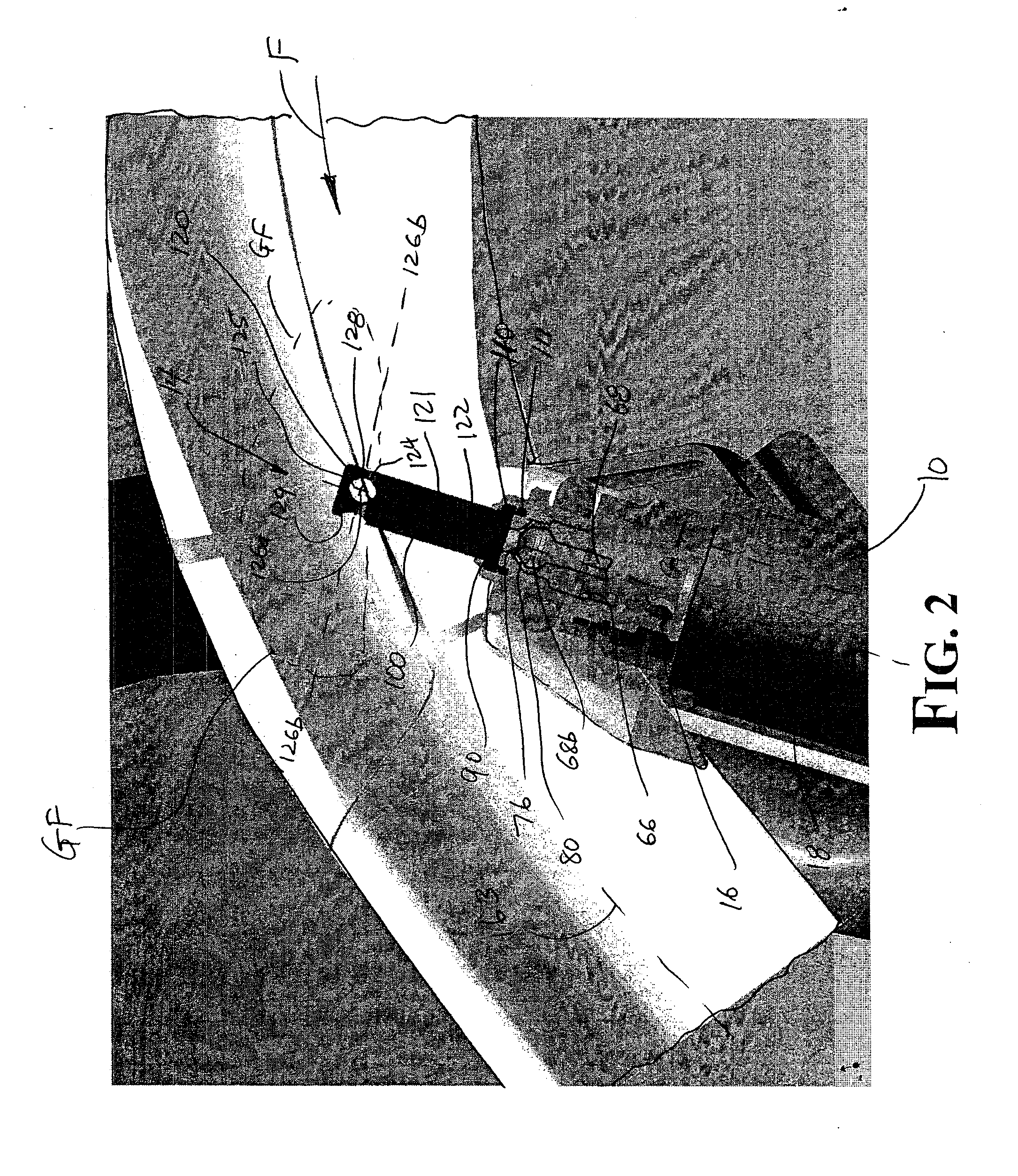
[0011]FIGS. 1-3 illustrate the preferred embodiments. In particular, FIG. 1 illustrates an intake manifold system 180 comprising an intake manifold 160 and a CNG fuel injector 10. A fuel rail 171 and a CNG fuel supply 172 are shown, but are not considered part of the intake manifold system 180.
[0012] The intake manifold 160 directs an air flow from an inlet 161 to an outlet 162. Outlets 162 are substantially tubular in shape and generally bolt to an engine block, not shown. The intake manifold provides combustion air to the combustion chamber(s) of the engine. The intake manifold 160 may be made of a metallic material, plastic, or other composite material. The intake manifold is preferably made of plastic, most preferably nylon 6-6.
[0013] The CNG fuel injector 10 has a housing, which includes a fuel inlet 12 (not shown), a fuel outlet 14, and a fuel passageway 16 extending from the inlet 12 to the outlet 14 along a longitudinal axis 18. The fuel outlet 14 of the CNG fuel injector ...
PUM
 Abstract
Description
Claims
Application Information
 - R&D
- Intellectual Property
- Life Sciences
- Materials
- Tech Scout
- Unparalleled Data Quality
- Higher Quality Content
- 60% Fewer Hallucinations
Browse by: Latest US Patents, China's latest patents, Technical Efficacy Thesaurus, Application Domain, Technology Topic, Popular Technical Reports.
© 2025 PatSnap. All rights reserved.Legal|Privacy policy|Modern Slavery Act Transparency Statement|Sitemap|About US| Contact US: help@patsnap.com


