Monitoring and in-line compensation of polarization dependent loss for lightwave systems

a technology of polarization dependent loss and lightwave system, which is applied in the direction of fibre transmission, distortion/dispersion elimination, electrical apparatus, etc., can solve the problems of wdm system, polarization dependent loss (pdl) is also a key limiting factor, and the practical scheme of fast pdl monitoring that is necessary for dynamic compensation has not been reported

Inactive Publication Date: 2008-02-14
UNIV OF SOUTHERN CALIFORNIA
View PDF11 Cites 5 Cited by
  • Summary
  • Abstract
  • Description
  • Claims
  • Application Information

AI Technical Summary

Benefits of technology

[0009] Embodiments of the present invention provide the first demonstration of a practical PDL monitoring scheme and a functional dynamic PDL compensator. They can be used for multi-wavelength, broadband compensation of polarization dependent loss, even in the presence of PMD through transmission fiber. The novel polarization scrambling method ensures fast and accurate in-line monitoring of PDL along a cascaded EDFA link. The applications of this invention include: (i) high bit-rate digital fiber transmission systems; (ii) reconfigurable optical networks; (iii) transmission of analog radio-frequency and millimeter-wave signals over fiber; (iv) dynamic compensation of polarization mode dispersion and polarization dependent loss in high-speed optical communication systems; (v) long-haul optical transmission; and (vi) analog fiber-optic system for wireless communications.

Problems solved by technology

It has become clear recently that polarization dependent loss (PDL) is also a key limiting factor in high-capacity wavelength multiplexing WDM) systems, because various optical networking components and erbium doped fiber amplifiers (EDFAs) may produce PDL.
Moreover, a practical scheme of fast PDL monitoring that is necessary for dynamic compensation has not been reported.
This scheme limits the PDL measurement time and / or accuracy in the presence of noise.

Method used


Image

  • Monitoring and in-line compensation of polarization dependent loss for lightwave systems
  • Monitoring and in-line compensation of polarization dependent loss for lightwave systems
  • Monitoring and in-line compensation of polarization dependent loss for lightwave systems

Examples


Embodiment Construction

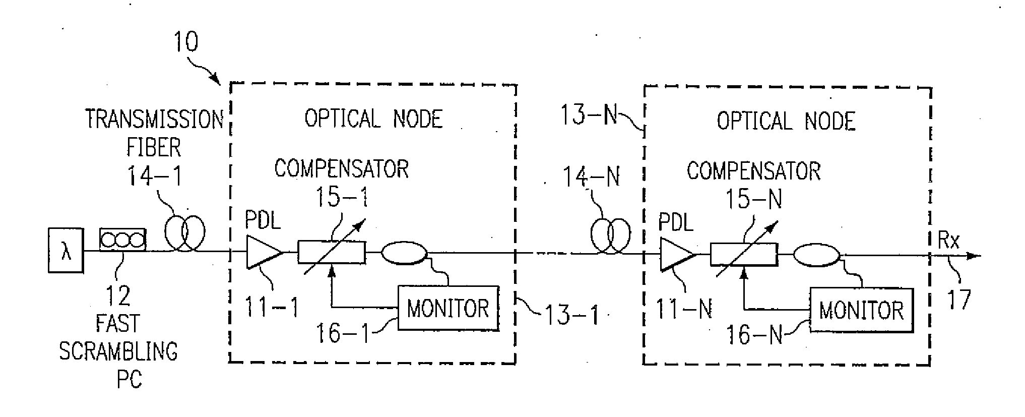
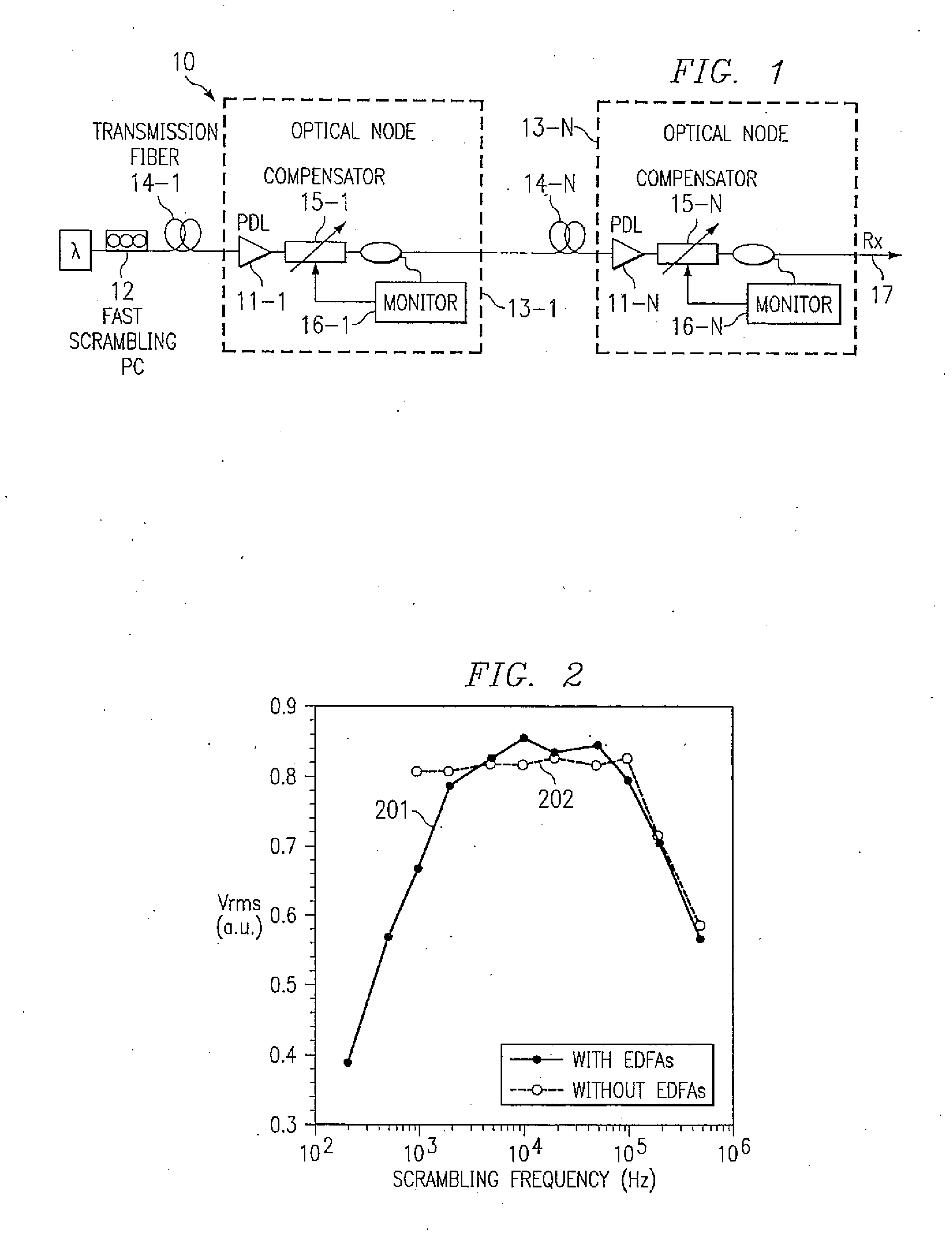
[0019]FIG. 1 illustrates in-line monitoring and dynamic compensation of PDL, in accordance with embodiments of the present invention. To monitor PDL along a cascaded EDFA link 10 and avoid the influence of EDFA transients, fast polarization scrambler 12 is inserted at the starting point of link 10. The PDL value is obtained from either the peak-to-peak variation or the standard deviation of the photo-detected signal' power. PDL 11-1, . . . , 11-N at every optical node 13-1, . . . , 13-N between transmission fibers 14-1, . . . , 14-N represents the unavoidable, deleterious polarization dependent loss in various active and passive optical components, for example EDFAs, optical switches, couplers, and / or isolators. Because the polarization coupling between these components may vary with time, the total PDL of the optical module or node 13-1, . . . , 13-N is also time-variable, making the dynamic monitoring and compensation of PDL valuable for optimization of overall system performance,...


PUM


Abstract

A multi-wavelength optical signal copropagates through a fiber-optic communication link with a continuous-wave ancillary wavelength having an unknown state of polarization (SOP), which is scrambled periodically in time. The instantaneous value of polarization dependent loss (PDL) in the ancillary wavelength is monitored in real time, and is used as an error signal to adjust at least one polarization controller. Polarization scrambling is performed by periodically changing the SOP with time, such that the polarization-scrambled optical signal covers approximately an entire Poincaré sphere surface, preferably uniformly, during each time period. At an optical node between fibers, an adjustable PDL compensator contains two ordered pairs each consisting of one polarization controller and one optical element introducing fixed PDL.

Description

CROSS-REFERENCE TO RELATED APPLICATIONS [0001] This application claims priority benefit of U.S. Provisional Application 60 / 276,799 filed Mar. 16, 2001.STATEMENT REGARDING FEDERALLY SPONSORED RESEARCH OR DEVELOPMENT [0002] The invention was made in part with Government support by Defense Advanced Research Projects Agency (DARPA) under the Air Force Grant Number: F30602-98-1-0196. The Government has certain rights in the invention.BACKGROUND OF THE INVENTION [0003] High data rate optical fiber communication is one of the fastest growing areas in the telecommunication industry. Compensation of lightwave polarization effects is one of the key enabling technologies for high-speed and long haul data transmission. There has been much interest in the limitations of high-speed lightwave systems caused by the stochastic nature of polarization mode dispersion (PMD). It has become clear recently that polarization dependent loss (PDL) is also a key limiting factor in high-capacity wavelength mul...

Claims


Application Information

Patent Timeline
Patent Type & Authority Applications(United States)
IPC IPC(8): H04B10/04H04B10/06
CPCH04B10/2572
Inventor YU, QIANYAN, LIANSHANWILLNER, ALAN E.
Owner UNIV OF SOUTHERN CALIFORNIA
Why Eureka
Try Eureka