
Electronic device hanging mechanism

a technology of electronic devices and hanging mechanisms, applied in the direction of identification means, instruments, lighting support devices, etc., can solve problems such as not being able to achieve optimal design

Inactive Publication Date: 2008-02-14
HANNSPREE INC
View PDF11 Cites 2 Cited by
  • Summary
  • Abstract
  • Description
  • Claims
  • Application Information

AI Technical Summary

Benefits of technology

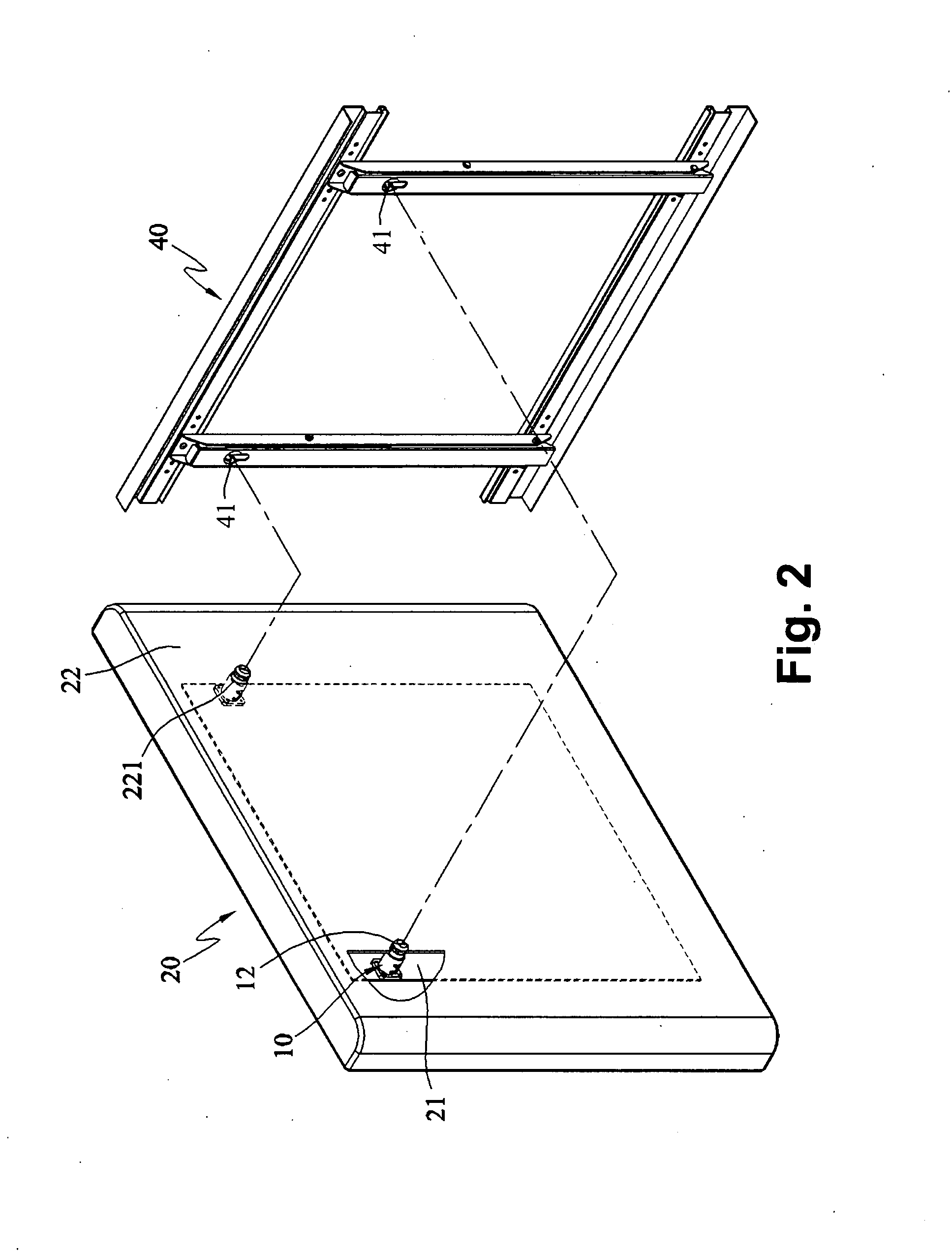
[0009] The electronic device hanging mechanism of the present invention can be directly located in the case of the electronic device. Besides, the bracing strut can be selectively moved to the holding position for storing the bracing strut or the hanging position for hanging the electronic device. When adopted for the flat display, it can quickly hang the flat display on the wall. The gap between the flat display and the wall is smaller. The hanging mechanism may also be hidden according to user's requirements. It is an optimal design for hanging the flat display.

Problems solved by technology

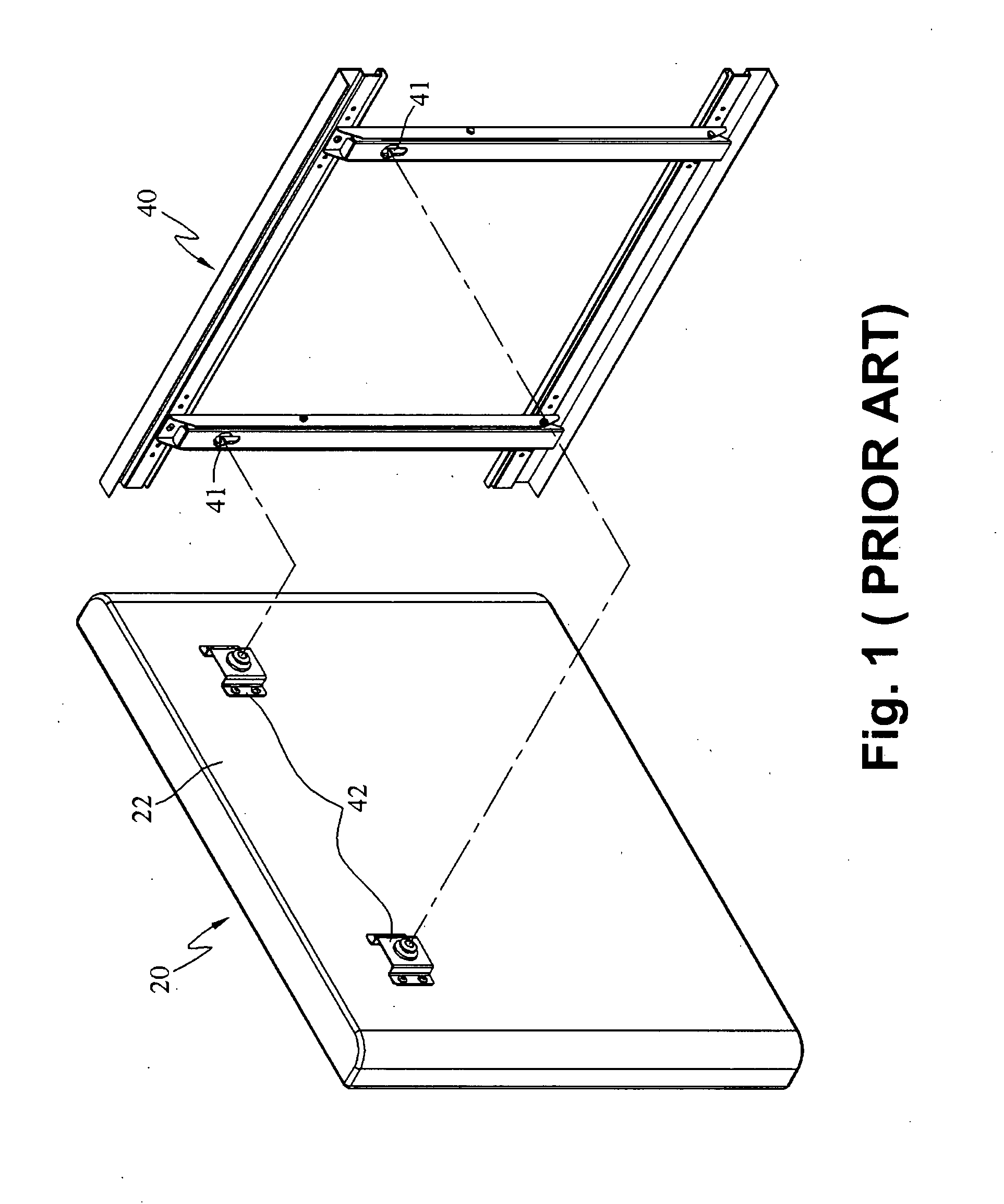
The aforesaid conventional techniques for hanging a thin display do not fully take into account user's requirements and also do not consider the total design of the flat display, so they are not the optimal design.

Method used


Image

  • Electronic device hanging mechanism
  • Electronic device hanging mechanism
  • Electronic device hanging mechanism

Examples


first embodiment

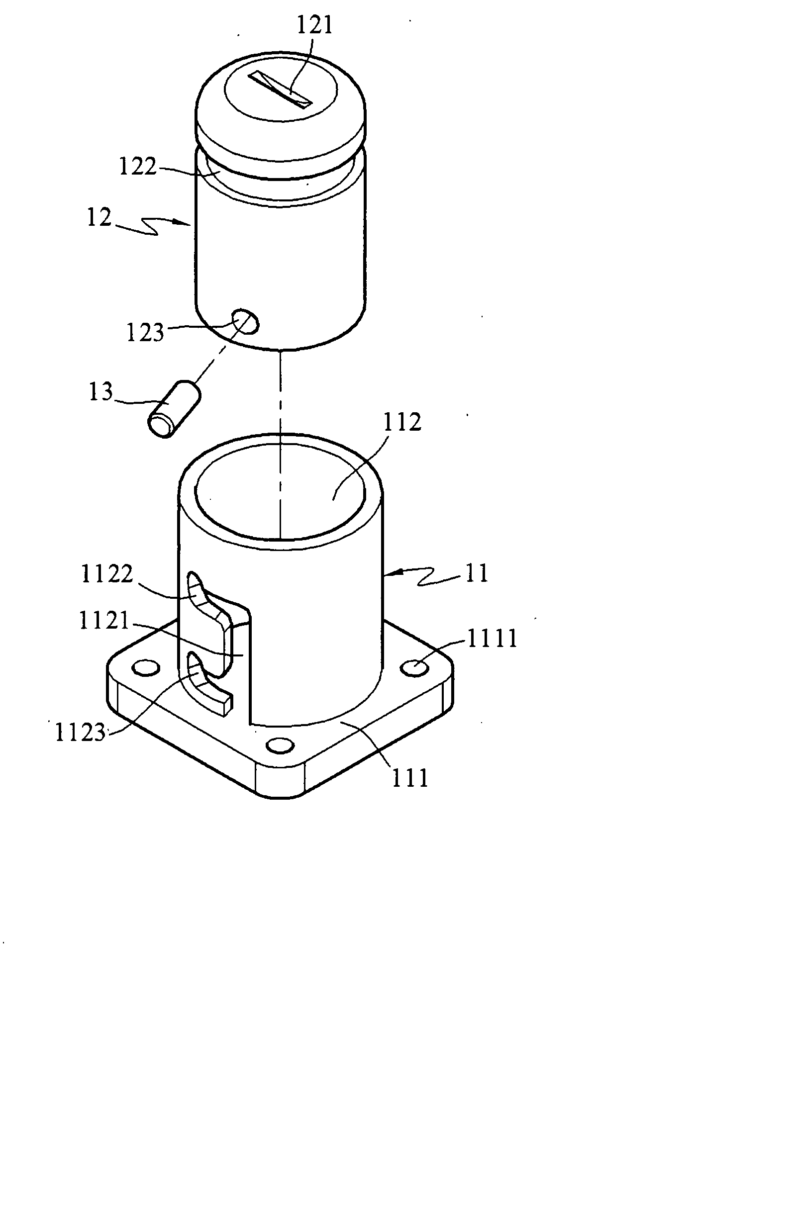
[0022] Referring to FIG. 2, according to a first embodiment of the electronic device hanging mechanism of the present invention, an electronic device 20 includes a base rack 21 to hold electronic elements (not shown in the drawing) of the electronic device 20. The electronic device 20 is covered by a case 22 to protect the electronic elements contained inside. The case 22 has a plurality of apertures 221 formed on desired locations according to the base rack 21. The hanging apparatus 10 of the electronic device hanging mechanism of the present invention includes a holding dock 11 (shown in the FIG. 3) and a bracing strut 12. Referring to FIG. 3, the holding dock 11 includes a base 111 and a hollow duct 112. The base 111 has a plurality of holes 111 to receive a plurality of screws (not shown in the drawings) to fasten the holding dock 11 to the base rack 21 (shown in the FIG. 5A) on the corresponding apertures 221 of the case 22. One end of the hollow duct 112 is extended from the b...

second embodiment

[0027] Referring to FIGS. 8A and 8B, for a second embodiment of the present invention, an electronic device hanging mechanism includes a holding dock 11a, a bracing strut 12a and a barrel 15a.

[0028] Compared with the first embodiment previously discussed, the second embodiment adds the barrel 15a with a guiding slot 151a, a first positioning slot 152a and a second positioning slot 153a. First, the bracing strut 12a is inserted into the barrel 15a and bonded with a pin 13a. Then the barrel 15a is inserted into the holding dock 11a. Such structure also can hide the bracing strut 12a. The rest of the mechanism and the operation method are the same as the first embodiment, so details are omitted.

third embodiment

[0029] As shown in the FIGS. 9A and 9B, for a third embodiment of the present invention, an electronic device hanging mechanism includes a holding dock 11b and a bracing strut 12b. The holding dock 11b includes a hollow duct 112b with internal screw threads 113b on the inner wall and the bracing strut 12b has external screw threads 124b on the peripheral surface, so the bracing strut 12b can be turned and then inserted into the holding dock 11b by engaging the internal screw threads 113b with the external screw threads 124b. It also can be implemented by using a tool into the insertion trough 121b to turn the bracing strut 12b. Hence the bracing strut 12b can be fully sunk into the holding dock 11b at the holding position, or be extended outside the holding dock 11b by turning to the hanging position.


PUM


Abstract

An electronic device hanging mechanism aims to hang an electronic device on a mounting rack mounted onto a wall. The hanging mechanism includes a holding dock located in the case of the electronic device and a bracing strut movably coupled on the holding dock. The bracing strut is extendable outside the holding dock at a hanging position to be hung on the mounting rack to hold the electronic device, and received in the holding dock and hidden in the case of the electronic device at a holding position to maintain the appearance of the electronic device.

Description

BACKGROUND OF THE INVENTION [0001] 1. Field of Invention [0002] The present invention relates to an electronic device hanging mechanism, and particularly to a hanging mechanism for hanging a thin display such as a liquid crystal display (LCD), plasma display, or surface-conduction electronic-emitter display (SED) on a wall. [0003] 2. Related Art [0004] In the past when people purchase television (TV) sets, the screen size was a main consideration. The TV set occupies a large space in a room, and a TV cabinet is also needed to support the TV set. The TV set is bulky and often affects the interior design. With the advance of the technology, electronic devices have become thinner and lighter. This is also true for home appliances. For instance, these days flat displays such as LCD TVs, plasma TVs and the like have been introduced to the market. The TV set has led this trend. [0005] With the introduction of flat display, the TV set no longer is limited to being rested on a TV cabinet. I...

Claims


Application Information

Patent Timeline
Patent Type & Authority Applications(United States)
IPC IPC(8): A47G29/00F16M13/02G09F9/35
CPCF16M13/02
Inventor LIN, CHANG-CHENG
Owner HANNSPREE INC
Learn More