
Connector for a Battery Terminal

Inactive Publication Date: 2008-01-31
TYCO ELECTRONICS FRANCE
View PDF9 Cites 2 Cited by
  • Summary
  • Abstract
  • Description
  • Claims
  • Application Information

AI Technical Summary

Benefits of technology

[0005]It is therefore an object of the present invention to provide a connector having an improved secured clamping of the connector to a terminal of a battery.
[0006]This and other objects are achieved by a connector for a terminal of a battery comprising an elastically deformable clamping member that receives the terminal of the battery. A lever is moveable relative to the clamping member between a locked posi

Problems solved by technology

As a result, incorrect fitting of the connector often occurs and results in poor electrical contact between the connector and the terminal and / or to a possible breakdown of the electrical contact therebetween.

Method used


Image

  • Connector for a Battery Terminal
  • Connector for a Battery Terminal
  • Connector for a Battery Terminal

Examples


Embodiment Construction

)

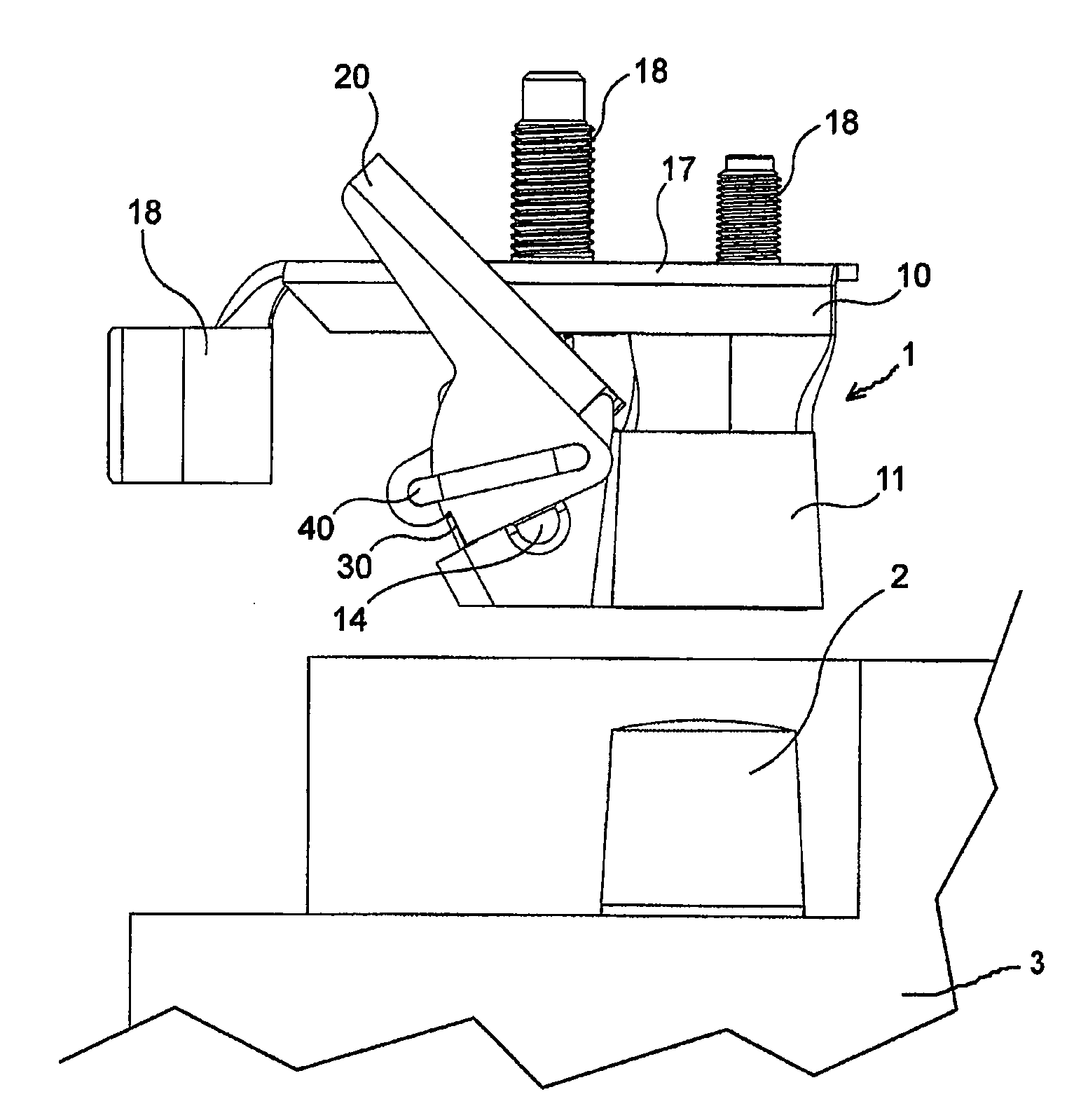
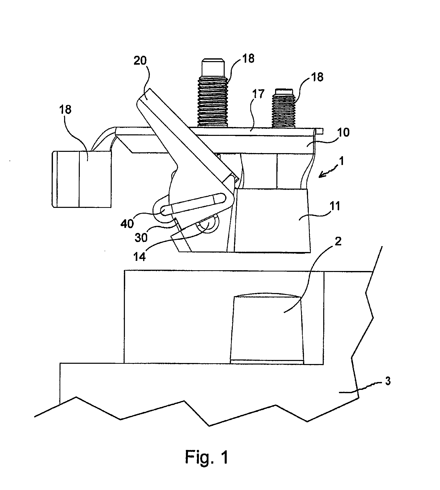
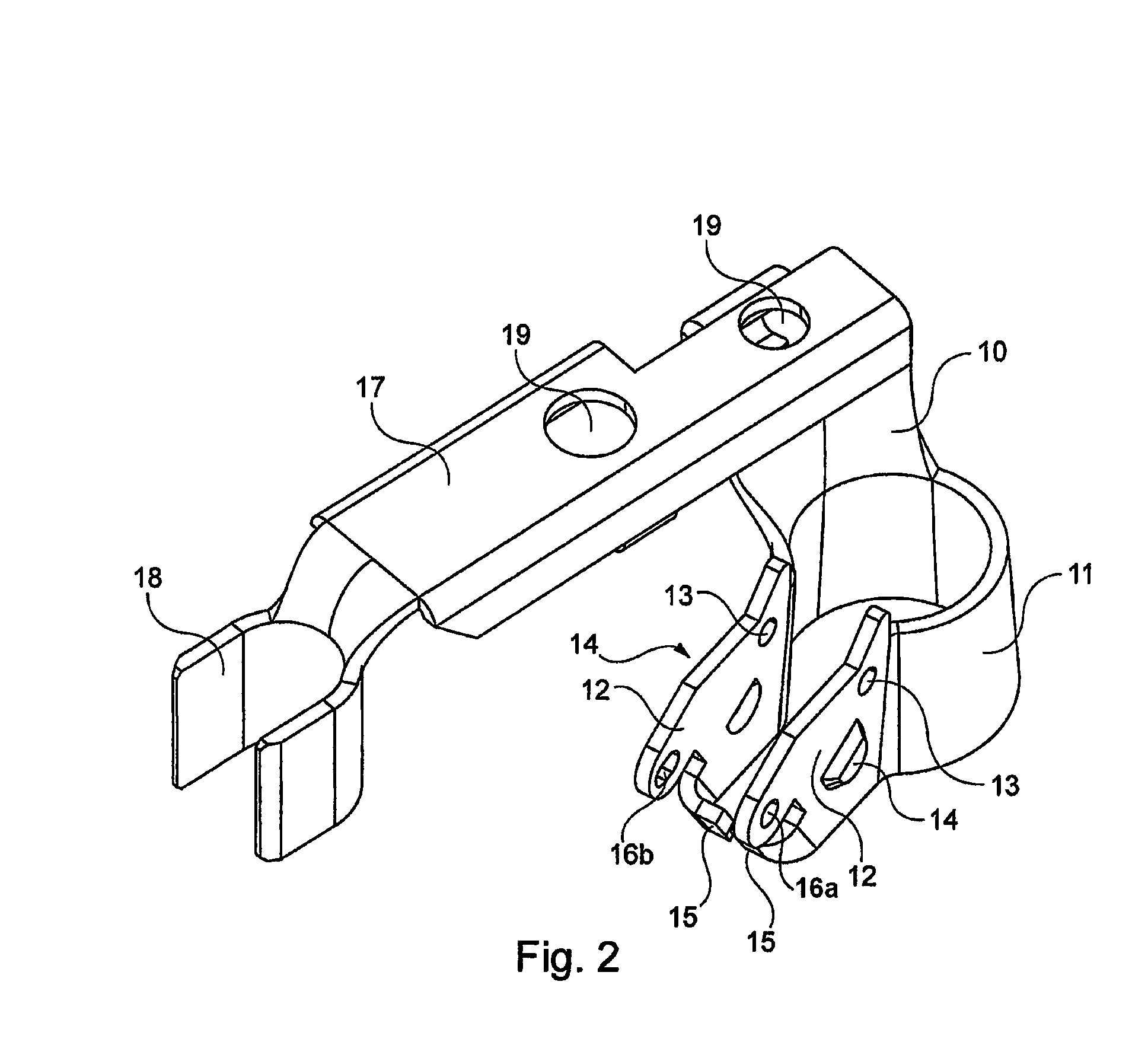
[0015]FIG. 1 shows a connector 1 for a battery terminal according to an embodiment of the invention. The connector 1 is configured to be fixed to a terminal 2 of an electric battery 3 and comprises a clamping lug 10, a clamping lever 20, a locking element 30, and a clip 40. As shown in FIG. 2, the clamping lug 10 includes a clamping member 11 and a connection portion 17. The clamping member 11 is configured to clamp the terminal 2 of the battery 3. The clamping member 11 is substantially U-shaped and includes elastically deformable arms 12. The arms 12 are substantially symmetrical and extend substantially parallel to each other. The arms 12 are configured to elastically deform toward each other. The arms 12 of the clamping lug 10 are configured to receive an element for clamping the clamping lug 10, for example, the clamping lever 20, in such a way that the lever 20 can move relative to the clamping lug 10 in order to clamp the clamping lug 10. Each of the arms 12 is provided with...


PUM


Abstract

A connector for a terminal of a battery includes an elastically deformable clamping member that receives the terminal of the battery. A lever is moveable relative to the clamping member between a locked position and an unlocked position. The lever applies a clamping force to the clamping member in the unlocked position. A locking element engages the lever in the locked position to prevent movement thereof. The locking element is elastically deformable such that the locking element releases the lever when the clamping member receives the terminal of the battery so that the lever is moveable to the unlocked position.

Description

CROSS-REFERENCE TO RELATED APPLICATIONS[0001]This application claims the benefit of the filing date under 35 U.S.C. § 119(a)-(d) of France Patent Application No. 0653186, filed Jul. 28, 2006.FIELD OF THE INVENTION[0002]The present invention relates to a connector for a battery terminal comprising a clamping lug for clamping the terminal of the battery and a lever for clamping the clamping lug.BACKGROUND[0003]Connectors are provided which are intended to be connected to either substantially cylindrical or truncated cone-shaped terminals on batteries that store electrical power. Connectors of this type are well known in the art, for example, from U.S. Pat. No. 2,819,455, U.S. Pat. No. 4,385,796, U.S. Pat. No. 5,556,309, and EP 0 896 389.[0004]Improving the secureness of the clamping of the connectors to the terminals of the battery is a key concern for designers. In practice, it has been found that the secureness of the connection to the terminal was dependent upon the correct fitting...

Claims


Application Information

Patent Timeline
IPC IPC(8): H01R11/01
CPCH01R13/62933H01R11/282
Inventor DOMPS, ETIENNE
Owner TYCO ELECTRONICS FRANCE
Learn More