
Frequency doubling fixation stimuli for visual field testing and therapy

Active Publication Date: 2008-01-31
NOVAVISION
View PDF21 Cites 39 Cited by
  • Summary
  • Abstract
  • Description
  • Claims
  • Application Information

AI Technical Summary

Benefits of technology

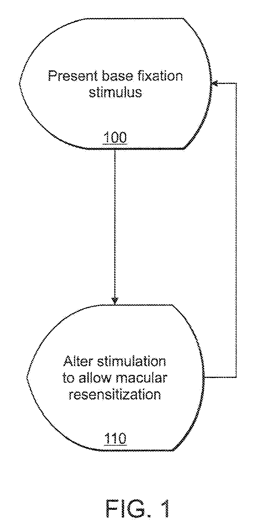
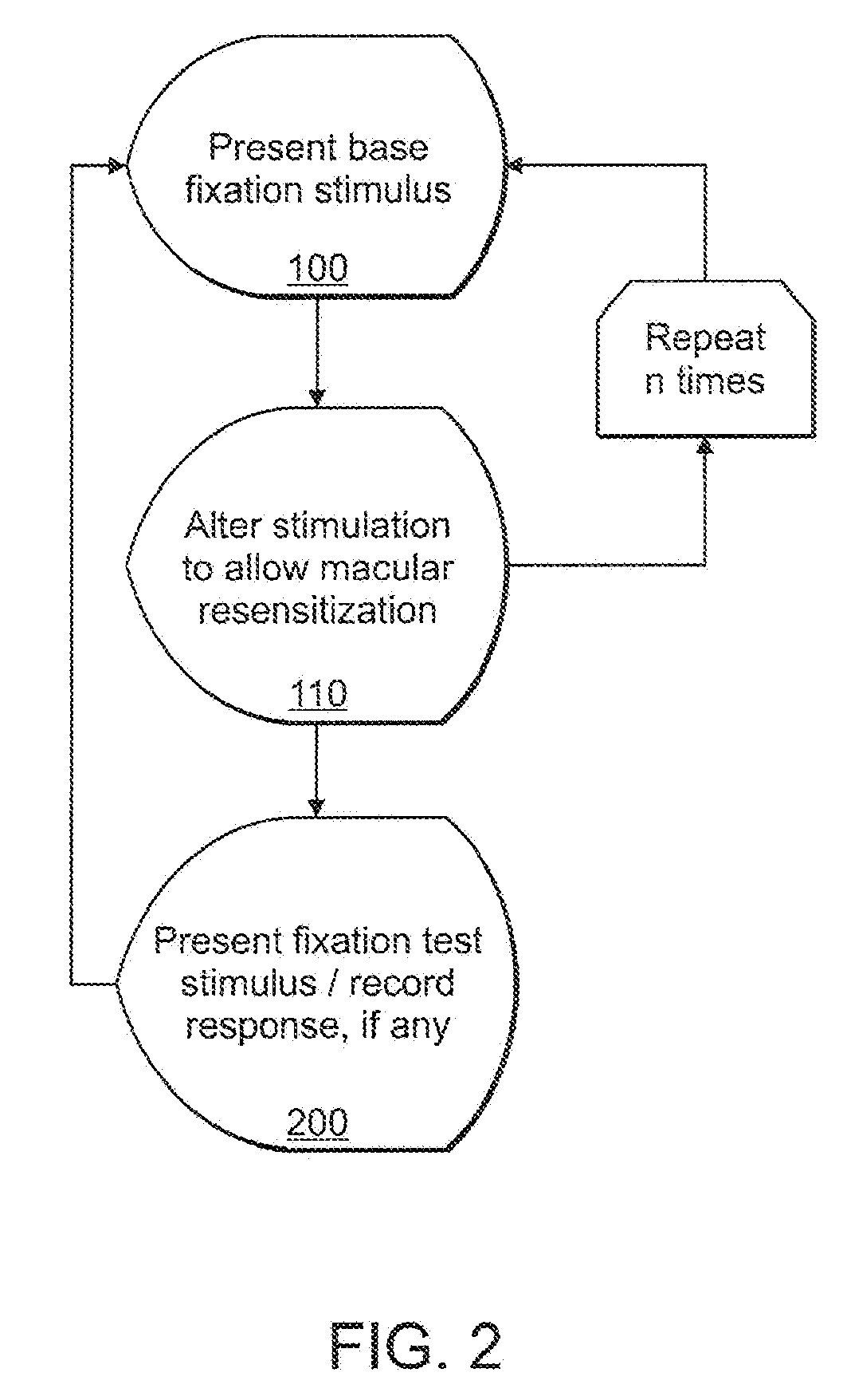
[0013] In accordance with an embodiment of the invention, alteration of a fixation stimulus displayed on a computer-driven display allows a human subject to maintain extended visual fixation upon the resulting dynamic stimulus. The fixation is presented upon the display and the stimulus is altered to allow resensitization of the subject's retina, thereby allowing prolonged visual fixation upon the resulting dynamic target.

Problems solved by technology

Such adaptation is problematic for devices requiring constant fixation upon a fixed point since the viewer must change fixation in order to continue seeing the object of regard.
This changing fixation may reduce the accuracy, precision, and overall effectiveness of testing, therapeutic, or non-therapeutic visual stimulation programs that require continuous unchanging visual fixation.
This disparity of functional loss and recovery can cause significant disharmony of the innately matched systems and resulting disturbances to the overall sensory function of the subject.
Current diagnostic testing modalities are limited in their ability to detect specific types of visual function damage.
However, neither technique is able to identify efficiently the amount or level of motion sensitivity at all the points within the borders.
Such as approach is not consistent with visual restoration therapy approaches that individually target small regions of the visual field.
Additionally, movement of a stimulus across a large region will tend to cause distraction of a patient, and is thus inconsistent with visual therapy approaches that utilize a fixation stimulus.
If patient feedback were collected with such a system, it would be difficult or even impossible to precisely locate the visual filed region that caused the patient's perception to be triggered.

Method used


Image

  • Frequency doubling fixation stimuli for visual field testing and therapy
  • Frequency doubling fixation stimuli for visual field testing and therapy
  • Frequency doubling fixation stimuli for visual field testing and therapy

Examples


example one

[0057] An isoluminous circular spot of small angular subtense (e.g. 11 pixels on an LCD monitor) is programmed to appear at pre-determined locations within the testing or therapy area of the applicable device. The circular spot of light “blinks” on and off at a pre-determined frequency but does not deviate from its original location.

example two

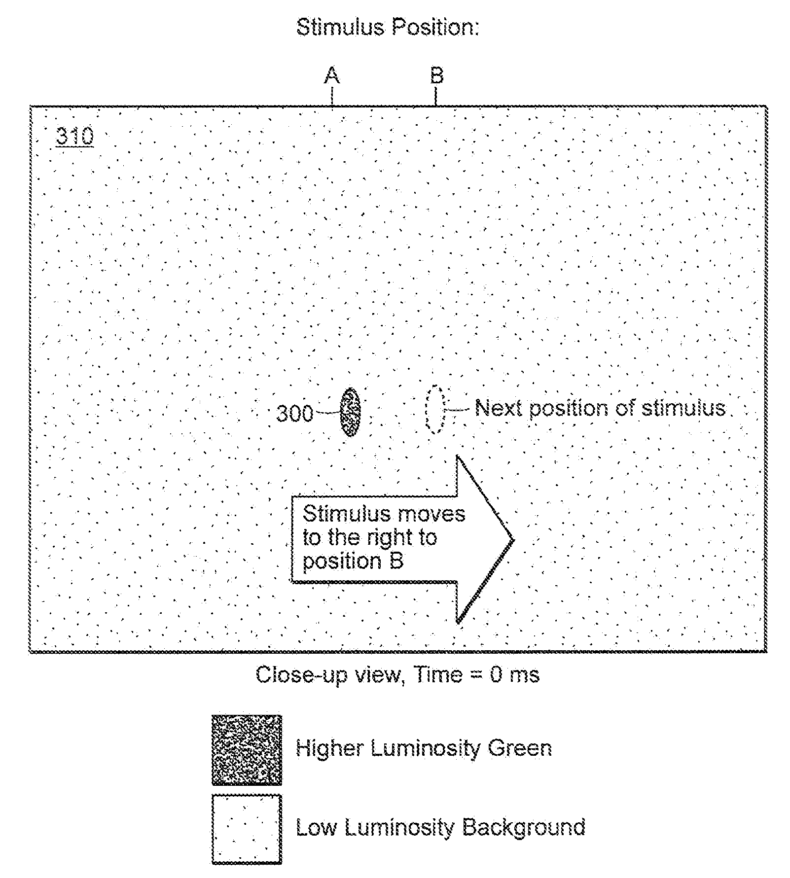
[0058] Two small (e.g. 5 pixels on an LCD screen), vertically elongated ellipses of light (paired side-by side) appear at a pre-determined location within the testing or therapy area and alternate illumination at a pre-determined frequency (e.g., right-left-right-left . . . ). The stimulus is modulated in appearance to trigger the percept of motion but the stimulus remains fixed in its location until detection or a pre-determined length of time.

[0059] In another embodiment of the invention, a frequency doubling grating may be used as a fixation stimulus in a way that creates an optical illusion. FIG. 21 shows a frequency doubling grating 850 as displayed upon a computer display in a brief moment of time. Like the frequency doubling gratings used for FDT, the spatial luminosity phase of the frequency doubling grating 850 is cycled above the critical flicker frequency, e.g., 25 Hz, to create a frequency doubling optical illusion. FIG. 22 shows how such an optical illusion might appea...


PUM


Abstract

Alteration of a fixation or peripheral stimulus displayed on a computer-driven display allows a human subject to maintain extended visual fixation upon the resulting dynamic stimulus. The fixation is presented upon the display and the stimulus is altered to allow resensitization of the subject's retina, thereby allowing prolonged visual fixation upon the resulting dynamic target. A dynamic stimulus may utilize a frequency doubling illusion.

Description

CROSS REFERENCE TO RELATED APPLICATIONS [0001] This patent application claims priority from U.S. Provisional Application Ser. No. 60 / 833,199 filed on Jul. 25, 2006 and U.S. Provisional Application Ser. No. 60 / 867,499 filed on Nov. 28, 2006, which are incorporated by reference herein in their entirety.TECHNICAL FIELD [0002] The present invention relates to systems for maintaining the focus of a subject on a specified region of a display for purposes of testing or improving a subject's vision. BACKGROUND [0003] The macula is the region of the retina which is used for high acuity vision, as is typically required for reading. To diagnose macular damage, a patient may undergo various types of examinations, including automated perimetry or campimetry, in which the patient is positioned in front of a test surface and is asked to maintain focus on a target. A computer then actuates one or more light sources to present visual stimuli at specific points on the test surface. The patient is ask...

Claims


Application Information

Patent Timeline
IPC IPC(8): A61B3/02
CPCA61B3/0091A61B3/024A61H5/00
Inventor TODD, DAVID
Owner NOVAVISION
Learn More