
Ticket Entry Systems and Methods

a ticket entry system and ticket technology, applied in the field of ticket entry systems and methods, can solve the problems of inaccurate information collected through the call center, people often injured in manual operation or using light or heavy equipment, and often struck by facilities

Inactive Publication Date: 2008-01-24
CELERITAS TECH L L C
View PDF8 Cites 140 Cited by
  • Summary
  • Abstract
  • Description
  • Claims
  • Application Information

AI Technical Summary

Benefits of technology

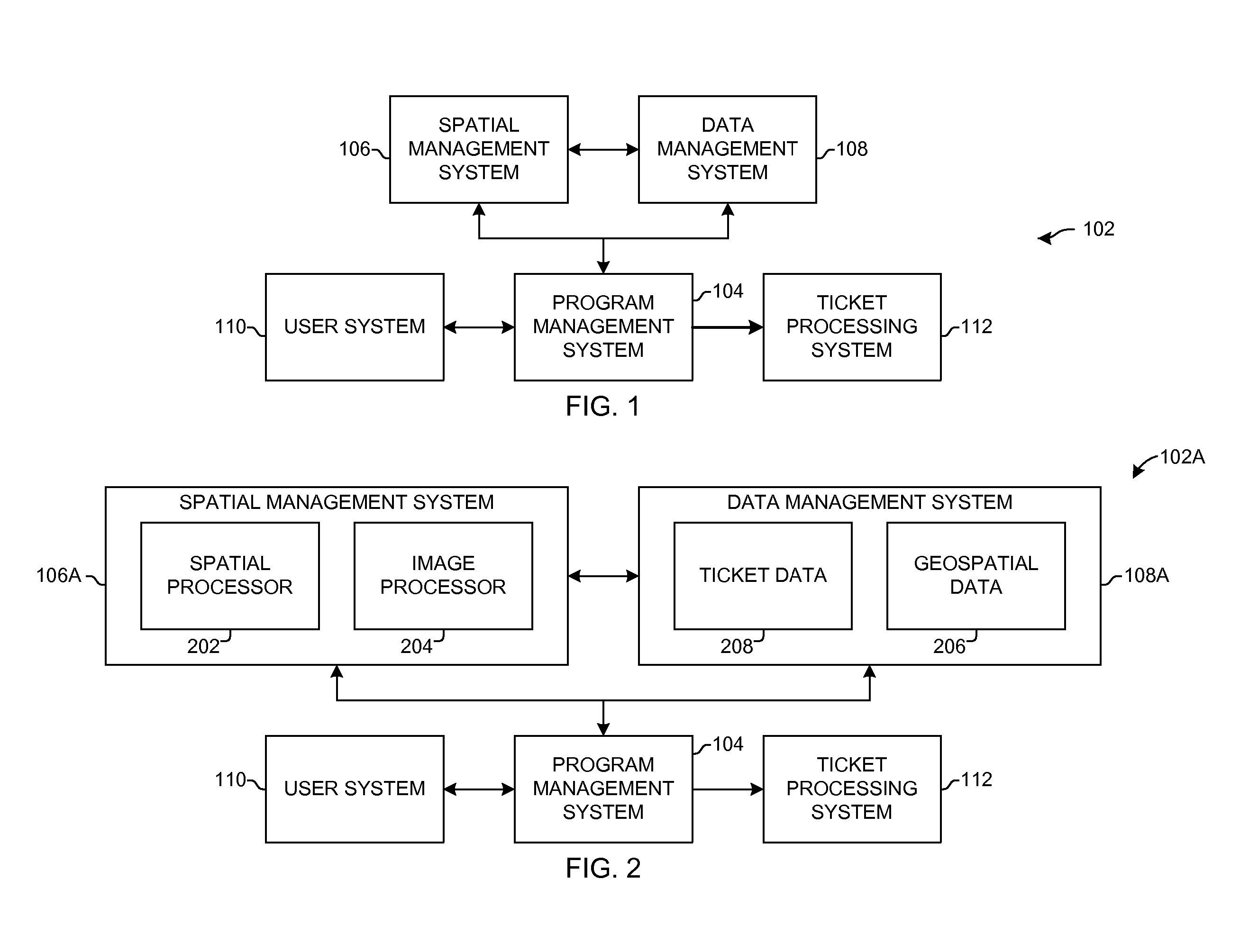
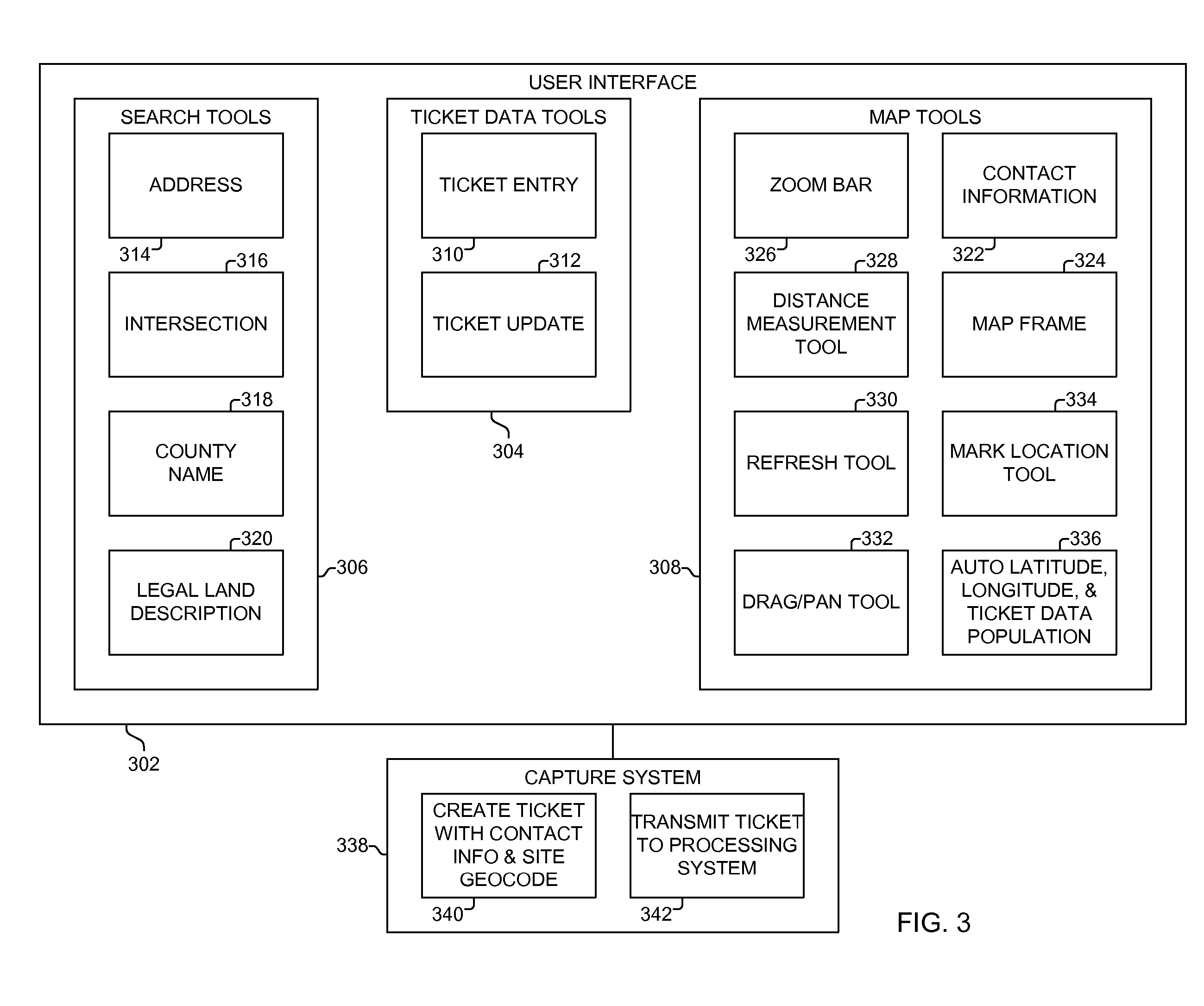
"The patent describes a ticket entry system that uses a program management system, a spatial management system, a data management system, and a user interface. The system allows users to request a locate ticket for a specific site location and provides them with a map of the area around the site. The system also allows users to create their own locate tickets by geocoding the site location and their contact information. The technical effect of this system is to streamline the ticket entry process and make it easier for users to find specific locations and access information about the area around them."

Problems solved by technology

The facilities are often struck by residents, excavators, and other entities during digging, construction, and other operations because the people performing the operation are not aware of the underground facility.
When these facilities are struck, they often are damaged.
In addition, people manually performing the operation or using light or heavy equipment often are injured.
However, the information collected through the call centers often is not accurate or is otherwise flawed.
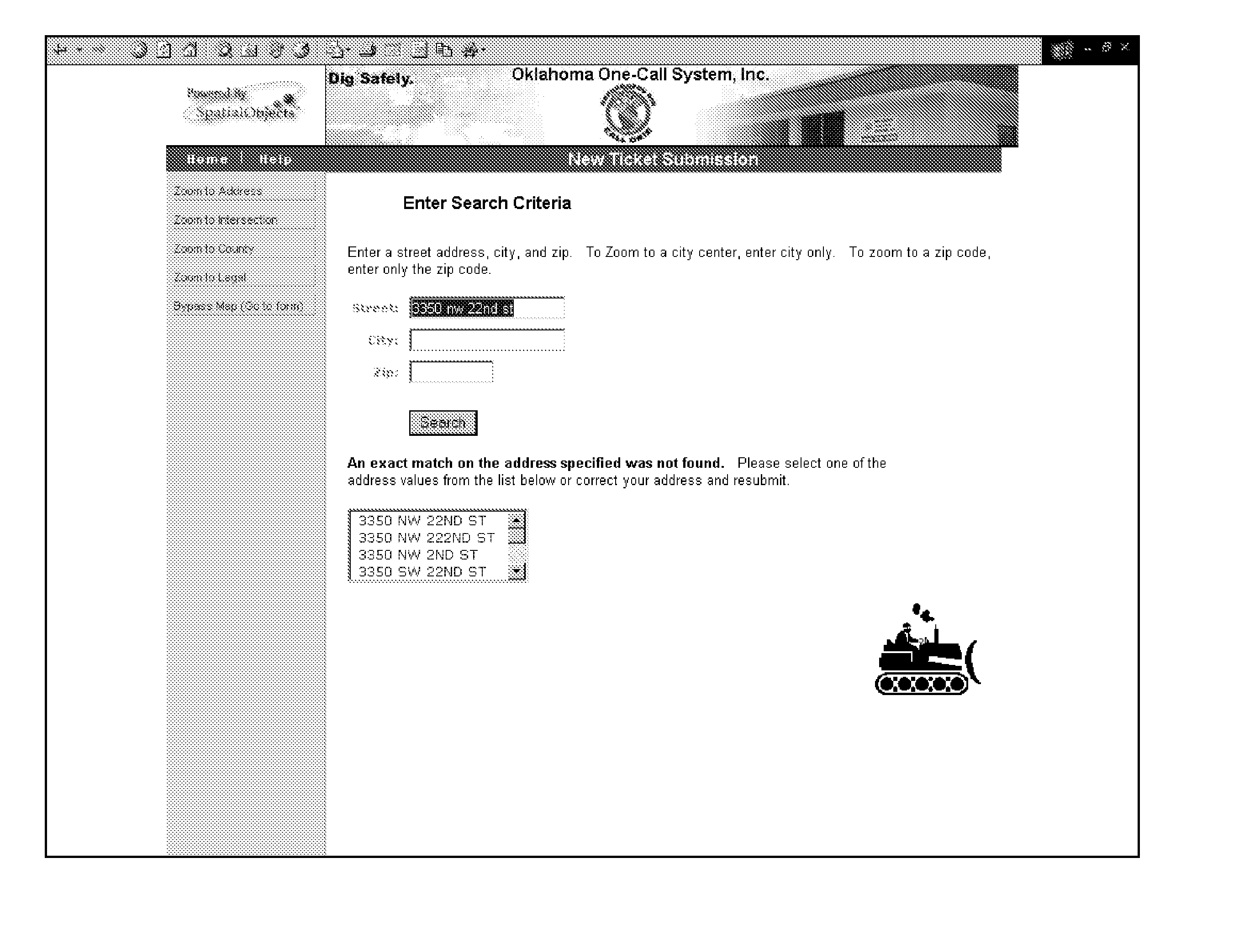
Unfortunately, this does not provide the exact location of the excavation, such as if more than one fence exists.
It does not provide information that would enable a customer service person to more accurately determine whether or not a facility is buried at or near the excavation site.

Method used


Image

  • Ticket Entry Systems and Methods
  • Ticket Entry Systems and Methods
  • Ticket Entry Systems and Methods

Examples


Embodiment Construction

[0015] The ticket entry (TE) system of the present invention enables a user to enter information when requesting that a location be identified for an operation. Such a request is sometimes referred to as a locate request, and it may be used, for example, by utility and state call centers to determine if the user may perform the operation at the site location, such as to dig at the requested site location.

[0016] The TE system of the present invention provides a user with a quick, accurate, and simple way to mark a location of an operation, including an excavation operation, a construction operation, underground boring or other boring, trenching, a facility operation, such as installation, maintenance, or removal of a utility or communication line or pipe, or another operation. The TE system of the present invention may be used for other operations, including determining whether or not the user is complying with regulations, such as regulations requiring a selected distance for const...


PUM


Abstract

In one embodiment, a ticket entry system and method include a program management system, a spatial management system, a data management system, and a user interface. The program management system receives contact information and a search criteria for a locate request. The program management system transmits the search criteria to the spatial management system. The spatial management system geocodes the search criteria and retrieves map data from the data management system corresponding to the search criteria geocode. The spatial management system transmits the map data to the program management system. The program management system transmits the map data to the user system and, in return, receives an indication of a site location where the operation is to be performed. The program management system transmits the site location indication to the spatial management system. The spatial management system geocodes the site location indication and transmits the site location geocode to the program management system. The program management system creates a locate ticket, which comprises the site location geocode and the contact information.

Description

RELATED APPLICATIONS [0001] This application is a continuation of U.S. patent application Ser. No. 10 / 965,989, filed Oct. 15, 2004, entitled Ticket Entry Systems and Methods, the entire contents of which are incorporated herein by reference.FEDERALLY SPONSORED RESEARCH OR DEVELOPMENT [0002] Not Applicable COMPACT DISK APPENDIX [0003] Not Applicable BACKGROUND OF THE INVENTION [0004] Utility companies, communications companies, governmental entities, and other entities sometimes locate utility and communication pipes and lines and other facilities underground. For example, power lines and gas lines sometimes are located underground. The facilities are often struck by residents, excavators, and other entities during digging, construction, and other operations because the people performing the operation are not aware of the underground facility. [0005] When these facilities are struck, they often are damaged. In addition, people manually performing the operation or using light or heavy...

Claims


Application Information

Patent Timeline
Patent Type & Authority Applications(United States)
IPC IPC(8): G06F17/30
CPCG06F17/30241
Inventor EVANS, SCOTT A.MARSHALL, ROBERT LEECUDD, STEVEN BRUCE
Owner CELERITAS TECH L L C
Learn More