
Scheduler, radio base station apparatus including the scheduler, and scheduling method

a radio base station and scheduler technology, applied in the direction of radio transmission, electrical equipment, transmission control/equalisation, etc., can solve the problems of increasing the reception end, reducing and high error rate in the radio segment, so as to ensure the coverage of the cell and the effect of effective use of radio resources

Inactive Publication Date: 2008-01-17
FUJITSU LTD
View PDF8 Cites 8 Cited by
  • Summary
  • Abstract
  • Description
  • Claims
  • Application Information

AI Technical Summary

Benefits of technology

[0019]With the foregoing problems in view, it is an object of the present invention to make it possible to realize effective use of radio resources following the instantaneous variation of radio quality and to assure the coverage of a cell.

Problems solved by technology

When radio propagation environment is deteriorated, an error rate in a radio segment becomes high.
In addition, when the error rate in a radio segment becomes high, opportunities of transmission of NACK which indicates abnormal reception on the reception end are increased, and the turn-around of the packet is lengthened.
However, the MaxCIR method causes a blind sector in which communication is not available, because radio resources are not allocated to users located in an area, such as a cell edge, in which radio quality is poor.
Here, when such fairness is assured, the priority of users poorer in radio quality are higher, and thus, the fairness is assured with low throughput, so that the system use efficiency becomes poor.
However, since the upper layer is in charge of controlling, the control delay is large.
When the control delay is large, instantaneous variation of radio quality cannot be followed up.
Thus, radio resources are used in vain during control delay.

Method used


Image

  • Scheduler, radio base station apparatus including the scheduler, and scheduling method
  • Scheduler, radio base station apparatus including the scheduler, and scheduling method
  • Scheduler, radio base station apparatus including the scheduler, and scheduling method

Examples


Embodiment Construction

)

[0054]Preferred embodiments of the present invention are described in more detail below referring to the accompanying drawings.

[0055]Here, the present invention should by no means be limited to the embodiment described below, and various changes or modifications may be suggested without departing from the gist of the invention.

[A] One Preferred Embodiment

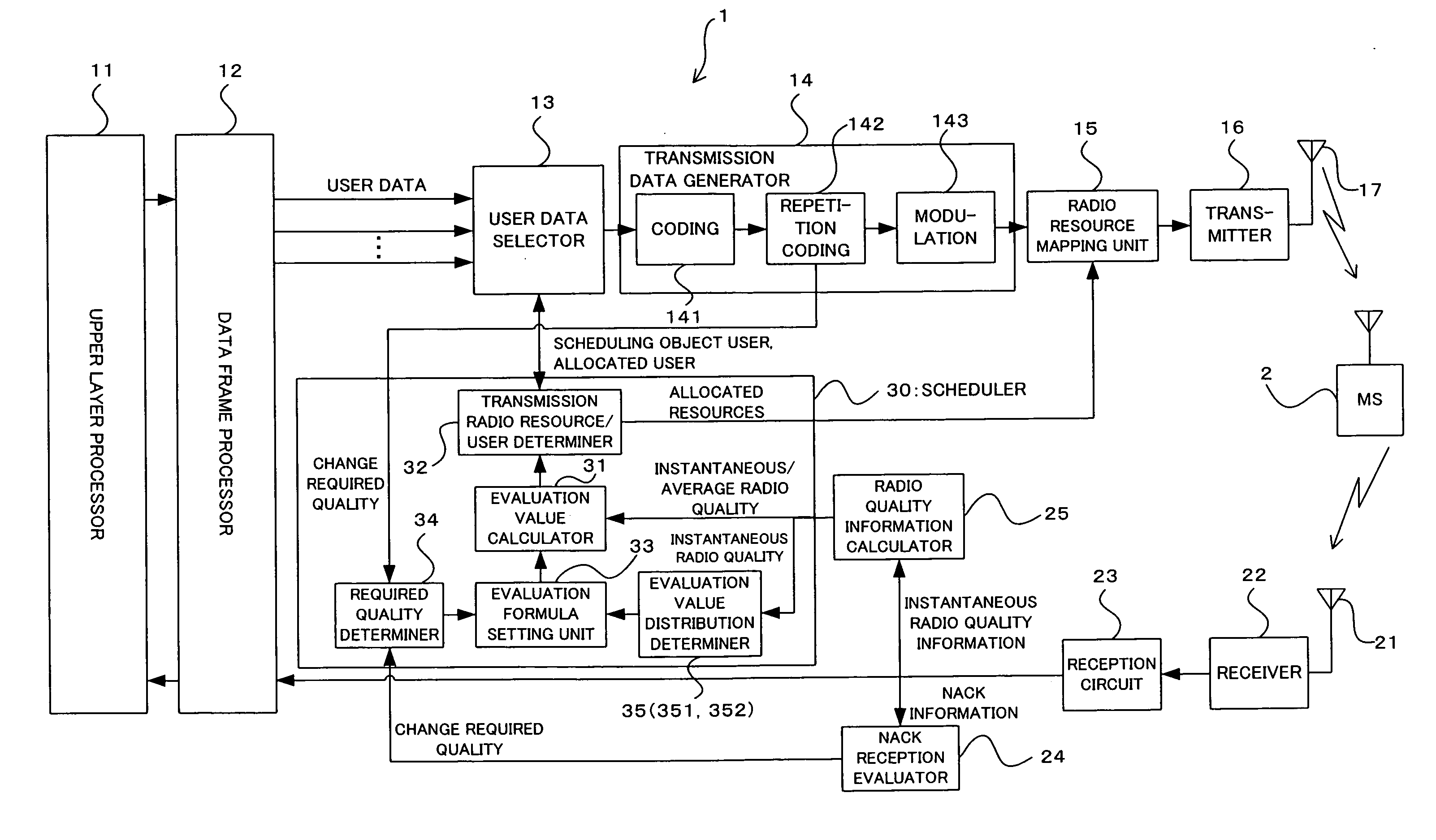
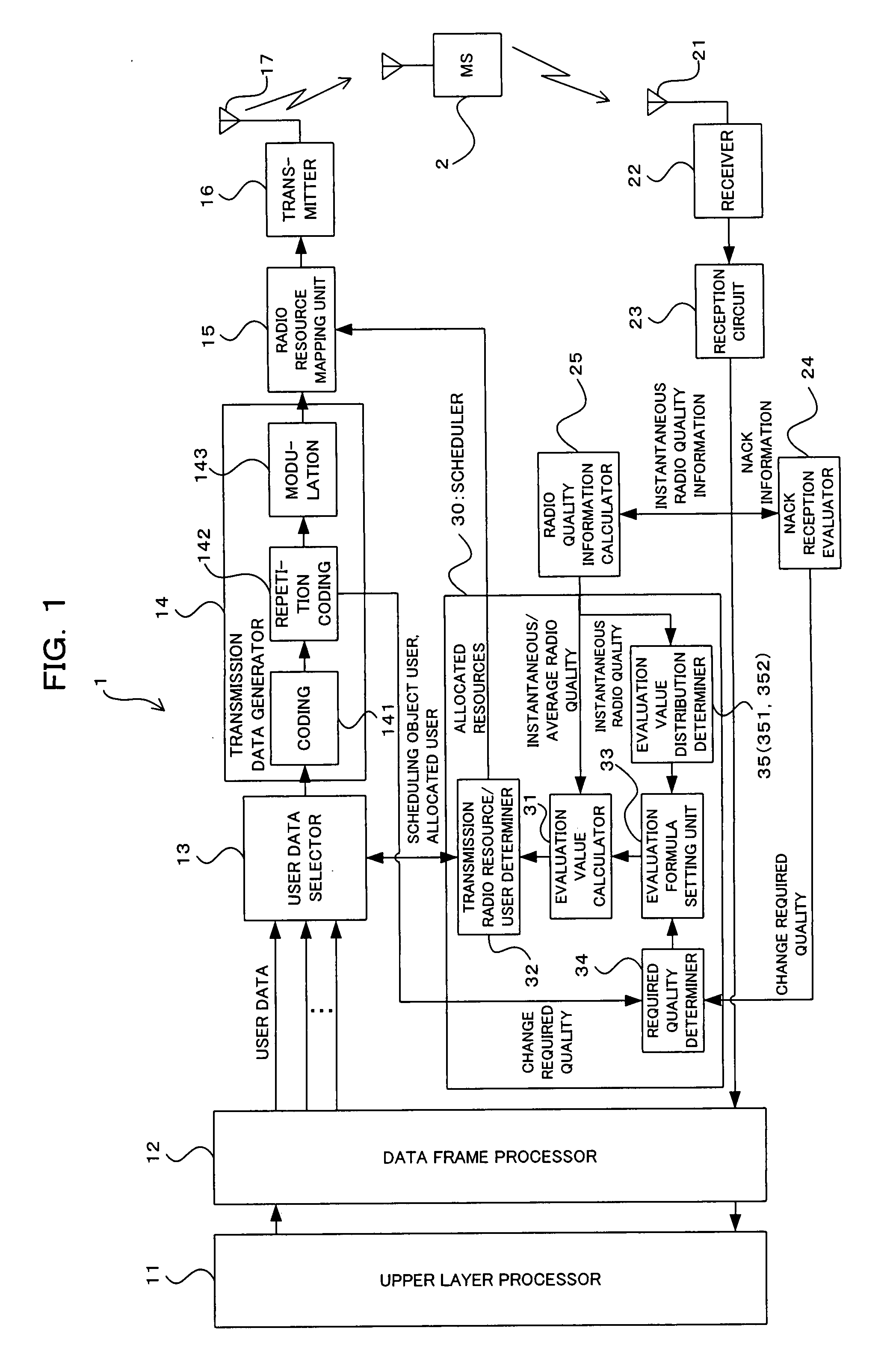
[0056]FIG. 1 is a block diagram showing an important construction of a radio base station apparatus (hereinafter will be simply called the “base station”) according to one preferred embodiment of the present invention. The base station 1 of FIG. 1 communicates with more than one mobile terminal (mobile station: MS) 2 by radio link (downlink from the base station 1 to the MS 2 and uplink which is its opposite direction). The base station 1 includes, for example, an upper layer processor 11, a data frame processor 12, a user data selector 13, a transmission data generator 14, a radio resource mapping unit 15, a transmitter 16, a tran...


PUM


Abstract

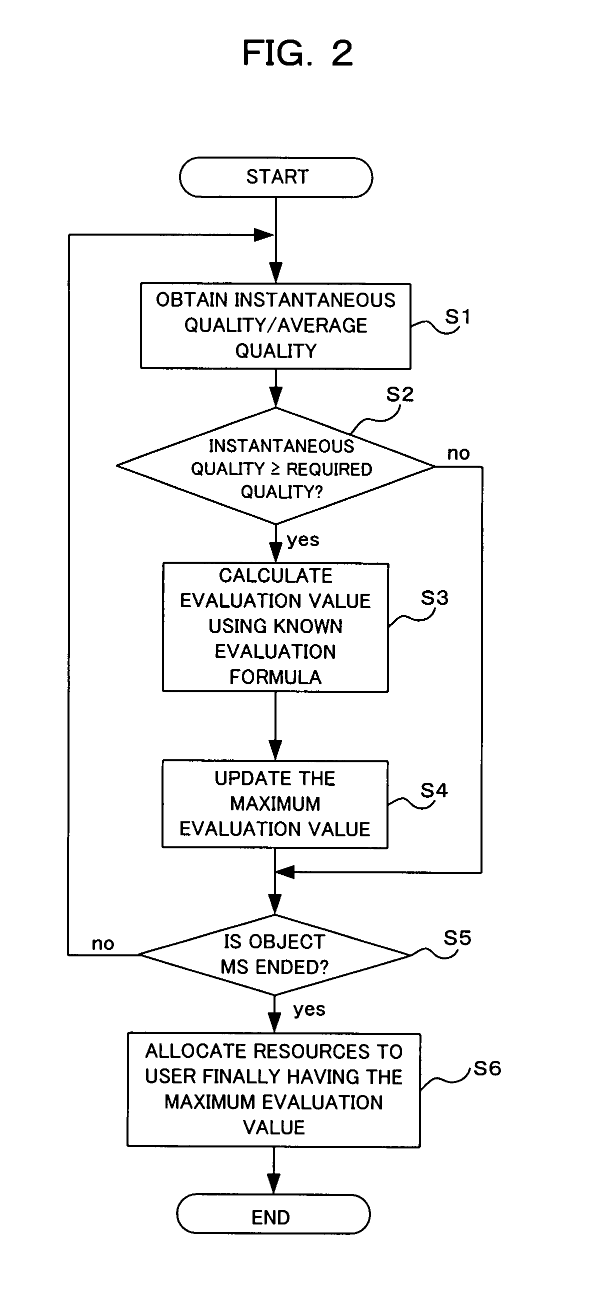
In the scheduler, for each of the mobile terminals which are the objects of scheduling, calculation is performed of an evaluation value relating to the priority of allocation of radio resources by means of a predetermined evaluation formula including radio quality information relating to radio quality between a base station and the mobile terminal; and controlling is performed of the evaluation value of a mobile terminal whose instantaneous radio quality is evaluated to be lower than the required radio quality by said radio quality evaluating means, to a value lower than an evaluation value of a mobile terminal whose instantaneous radio quality is evaluated to be equal to or higher than the required radio quality. As a result, it becomes possible to realize effective use of radio resources following the instantaneous variation of radio quality and to assure the coverage of a cell.

Description

CROSS REFERENCE TO RELATED APPLICATION[0001]This application is based on and hereby claims priority to Japanese Application No. 2006-190462 filed on Jul. 11, 2006 in Japan, the contents of which are hereby incorporated by reference.BACKGROUND OF THE INVENTION[0002](1) Field of the Invention[0003]The present invention relates to a scheduler, a radio base station apparatus including the scheduler, and a scheduling method. The invention relates to, for example, technology suitable for use in a radio base station apparatus in a radio mobile communication system.[0004](2) Description of the Related Art[0005]In a radio mobile communication system using packet communication, communication quality is monitored, and control is performed so that the transmission speed and the modulation method suitable for communication quality are adaptively selected. The reason of change in communication quality is variation in radio propagation environment, and it is often occurred that radio quality is in...

Claims


Application Information

Patent Timeline
Patent Type & Authority Applications(United States)
IPC IPC(8): H04Q7/30H04B7/005H04W72/54
CPCH04W72/085H04W72/10H04W72/087H04W72/543H04W72/542H04W72/56
Inventor FUJITA, HIROSHIYOSHIDA, MAKOTO
Owner FUJITSU LTD
Learn More