
Rotary cutting tool assembly

Active Publication Date: 2008-01-17
DART IND INC
View PDF19 Cites 16 Cited by
  • Summary
  • Abstract
  • Description
  • Claims
  • Application Information

AI Technical Summary

Benefits of technology

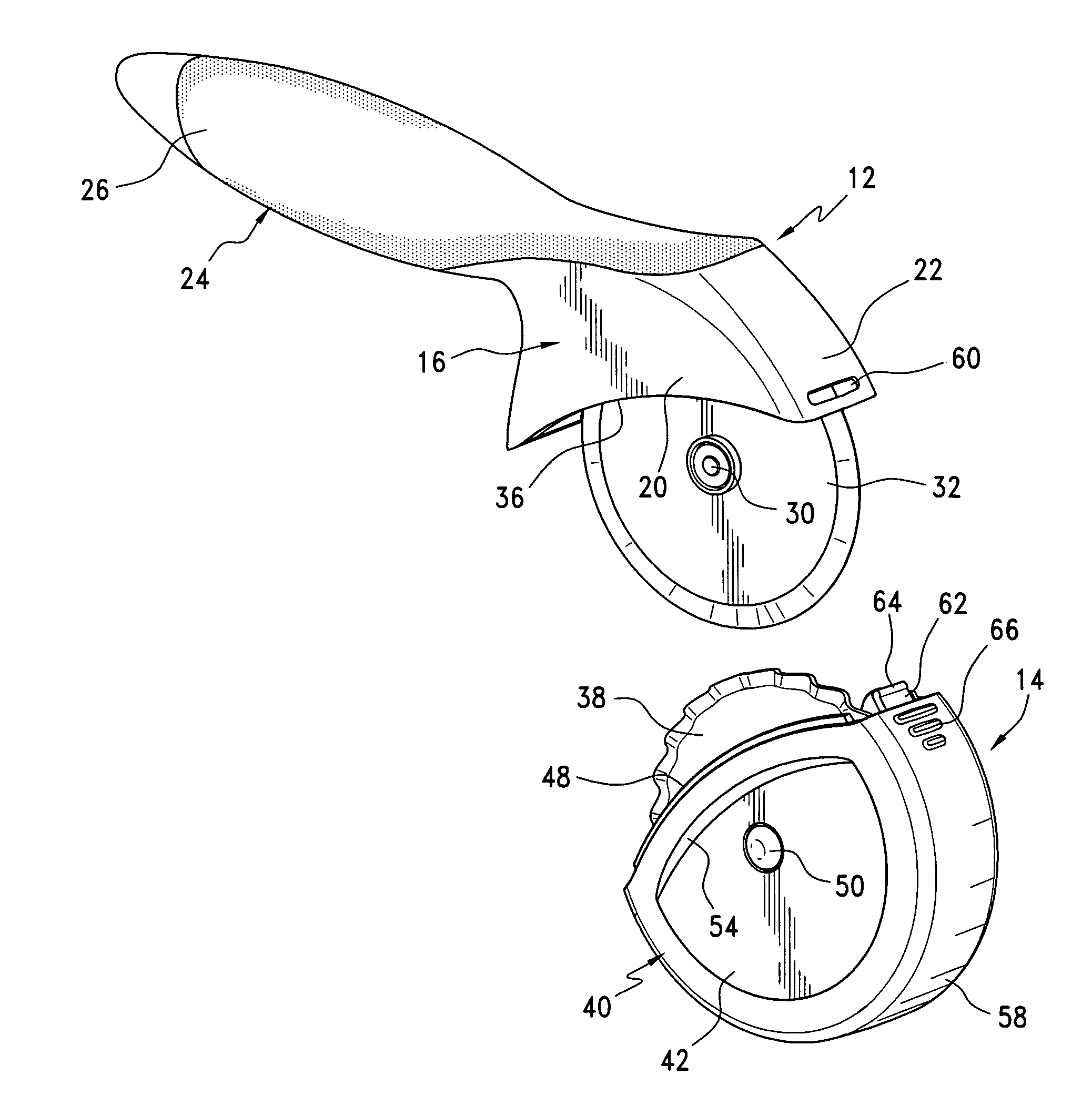
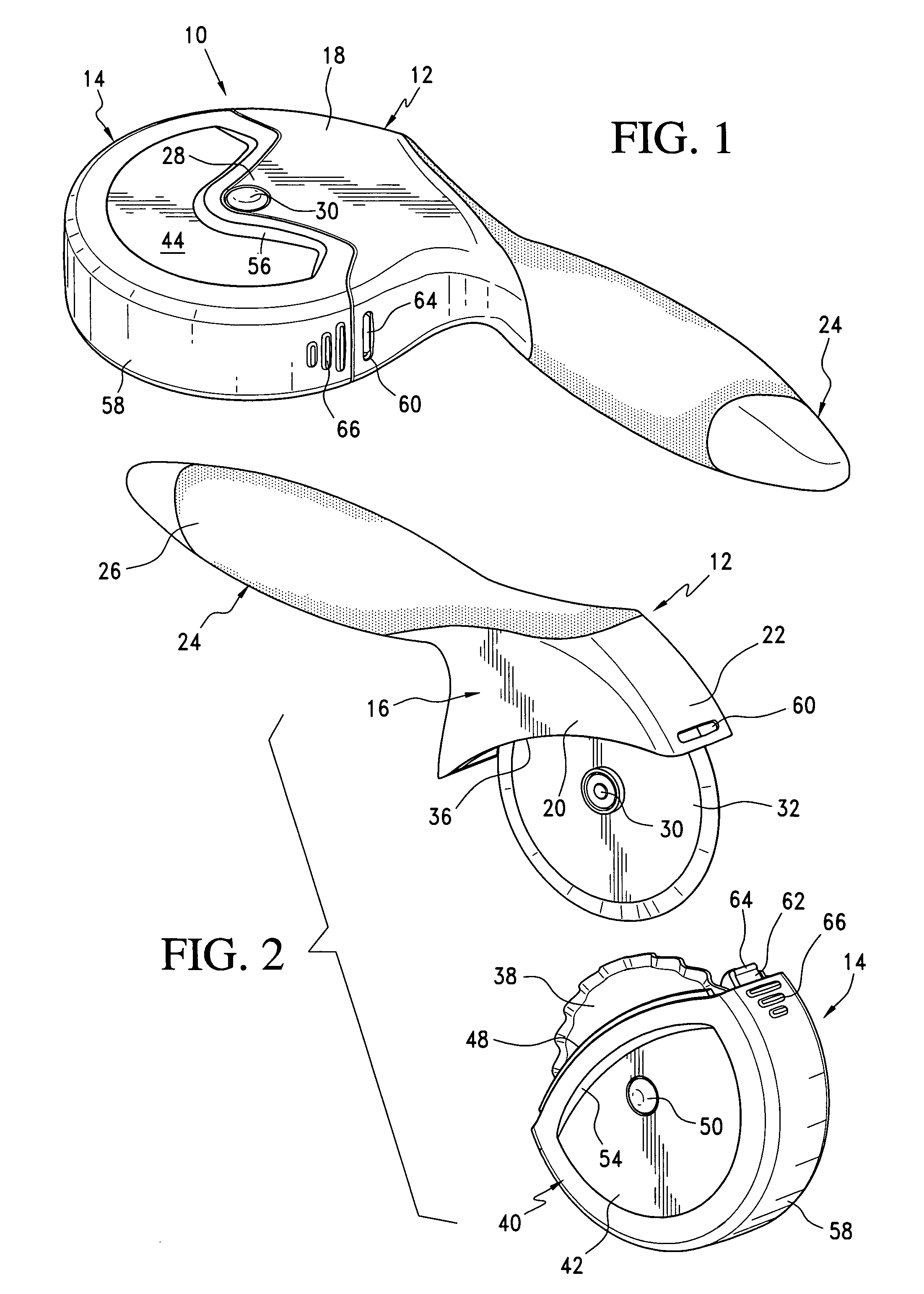
[0004]As will be seen in the preferred embodiment to be subsequently described, one of the tools may be considered the principal or primary cutter with the housing having an elongate ergonomic handle for manipulation of this tool in a manner similar to that associated with the known tools. As an example, such a tool may be particularly appropriate for use as a pizza cutter. The companion or secondary tool is in the nature of a cover. However, in addition to protectively enclosing and shielding the blade of the primary tool, the secondary tool also independently mounts a second rotating cutting wheel or blade which, as the cover encloses the primary tool blade, is itself received within the housing of the primary tool in spaced parallel relation to the blade therein with both blades thus being effectively concealed and protected and with the entire assembly forming a single unit for conveniently carrying by the elongate handle. The actual use of the secondary tool is easily affected through utilization of the housing or cover thereof as a handle. This tool, as an example, may be more appropriate for use in the cutting of pizza dough prior to the actual formation of the pizza itself. As desired, appropriate gripping means can be provided on the secondary tool cover for ease of manipulation as a handle.

Problems solved by technology

This in turn normally requires an awkward disassembly and reassembly of the operating components of the tool or a rather complex structural arrangement allowing for blade shifting.

Method used


Image

  • Rotary cutting tool assembly
  • Rotary cutting tool assembly
  • Rotary cutting tool assembly

Examples


Embodiment Construction

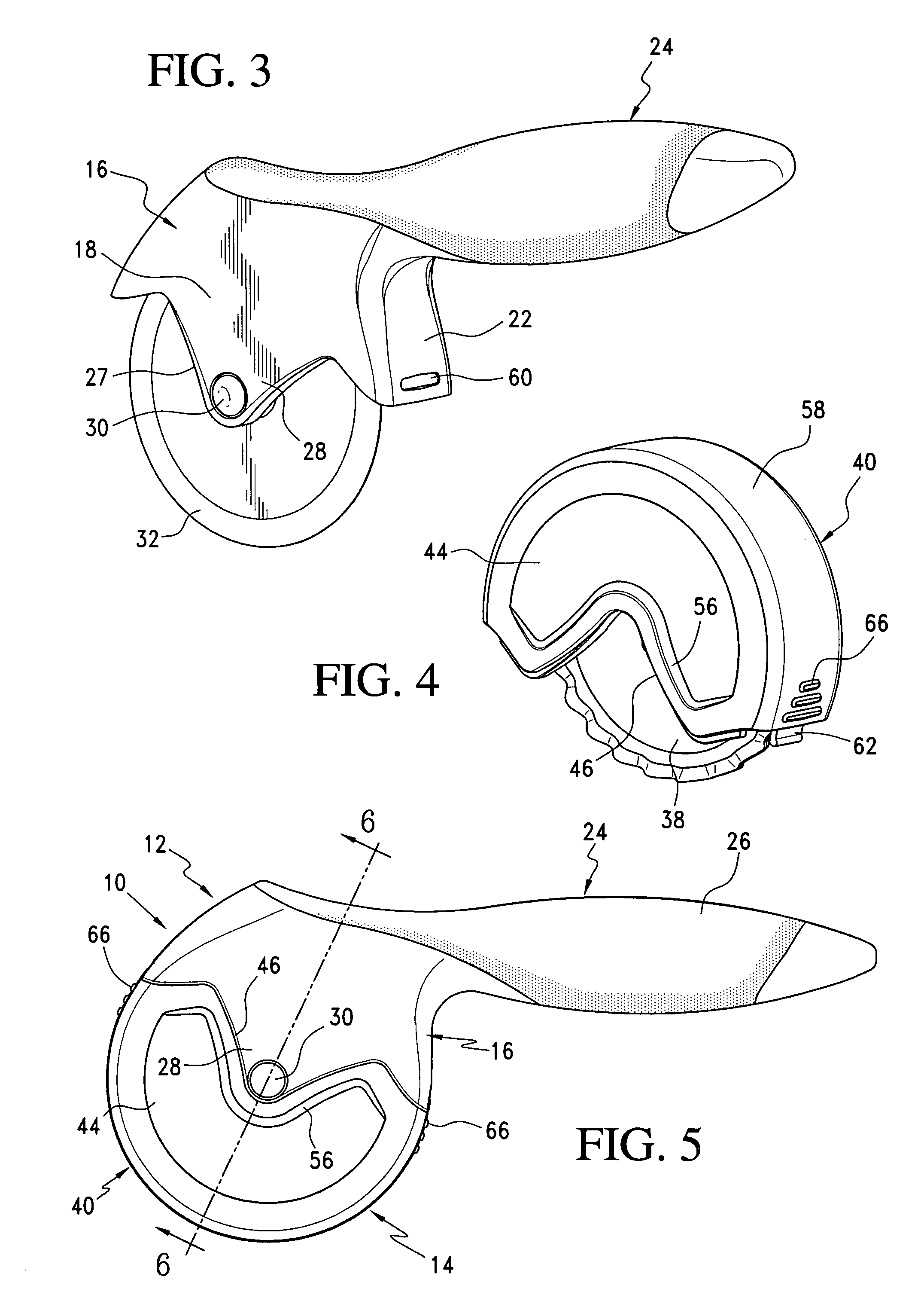
[0015]Referring now more specifically to the drawings, the tool assembly 10 consists basically of two major components, a primary tool 12 and a secondary tool or blade cover 14.

[0016]The primary tool 12 includes a downwardly opening housing 16 with laterally opposed first and second side walls 18 and 20 and a transverse top wall portion 22 joining the side walls 18 and 20 above the respective lower edges thereof. In order to handle and manipulate the rotary cutting tool 12, an elongate ergonomically configured handle 24 is integrally formed with the housing 16, and in particular, the transverse top wall 22 thereof, and extends laterally therefrom generally parallel to the side walls 18 and 20 for an easy grasping thereof. As desired, the handle 24 can be provided with an appropriate grip enhancing elastomeric insert 26 which extends about and along a major portion of the handle 24.

[0017]Noting FIG. 3 in particular, it will be seen that the side wall 18, along the lower or open edge ...


PUM


Abstract

A tool assembly comprising a primary tool including a housing internally mounting a rotary cutter blade with a portion of the blade exposed for a cutting action, and a cover for selectively protectively enclosing the cutter blade of the primary tool, the cover also including a housing mounting a second rotary blade partially exposed for cutting action upon utilizing the cover housing as a handle, the primary tool housing protectively enclosing the cover blade simultaneously with the cover protectively enclosing the primary tool blade upon engagement of the cover with the primary tool.

Description

BACKGROUND OF THE INVENTION[0001]The present invention relates to cutting tools incorporating rotary cutting wheels of the type normally considered for use as a kitchen implement or more particularly a cutter for pizza, dough, and like items. Such implements or tools are generally well known and are usually in the form of hand held implements mounting a rotating cutting wheel which rolls along and slices the particular foodstuff or product involved.[0002]Tools of this type, and the broadly related similar hand-held implements for the cutting of a wide variety of sheet materials, in addition to incorporating the rotatable cutting wheel itself, will be provided with a convenient handle and, in some instances, with some form of blade shield or guard. Such cutting tools have also, on occasion, been known to incorporate or utilize interchangeable blades to accommodate varying conditions. This has heretofore necessitated an actual adjustment of the tool to remove or displace one operating...

Claims


Application Information

Patent Timeline
IPC IPC(8): B26B3/00
CPCB26B25/005B26B11/00
Inventor KORTLEVEN, HANNOHEIBERG, JAKOB
Owner DART IND INC
Learn More