
Surface replacement of a femoral head

a femoral head and surface technology, applied in the field of femoral implants, can solve the problems of femoral implants not being femoral implants may not be sufficiently flush with the femoral head or on the femoral neck, and the procedure can be time-consuming

Inactive Publication Date: 2008-01-10
BRAINLAB
View PDF8 Cites 12 Cited by
  • Summary
  • Abstract
  • Description
  • Claims
  • Application Information

AI Technical Summary

Benefits of technology

[0010] The ascertained implant value can be compared with a predetermined limit value or a limit value derived, for example, from the base value of the femoral implant. If an implant value indicative of how many or what proportion of the ascertained reference point spatial positions are outside the inner diameter of the femoral implant model exceeds the limit value, then it may be deduced that the chosen femoral implant model is too small for the femoral head in question or is arranged in an incorrect position. In this case, the femoral implant model can be virtually moved, for example by shifting, to another predetermined or ascertainable position. In this new position of the femoral implant model, an implant value can again be ascertained, which may be compared with the predetermined limit value, wherein it is again possible to deduce from the comparison with the limit value whether an appropriate size and position of the femoral implant has been found or whether the femoral implant is to be repositioned again and checked again for appropriate size and shape. If the implant value falls below the limit value, it may be deduced that the femoral implant model exhibits a correct size and is correctly positioned, such that by taking these data into account, a surgeon, for example, can position a femoral implant having the ascertained size at the ascertained position.
[0011] If the implant value does not fall below the limit value in any of the positions, or exceeds it in every position, then a new femoral implant model having a larger size or inner diameter than the previous size or inner diameter is preferably calculated. The inner diameter of the femoral implant model, for example, can be increased by one, two or more units. The larger femoral implant model is preferably positioned again and checked for size and position at different positions by means of the implant value.

Problems solved by technology

If a femoral implant is selected that is too small (e.g., an inner diameter of the implant is too small) and cemented on the fraised head, there exists the danger that the fraiser apparatus that processes the inner contour of the implant is unintentionally fraised into the femoral neck so as to cause a fracture of the femoral neck.
If a femoral implant is selected that is too large, then the femoral implant may not be sufficiently flush with the femoral head or on the femoral neck.
This procedure can be time-consuming and can include a number of possible inaccuracies due to projection errors.
Further, the determined size may be intra-operatively verified by means of measuring templates or metal templates, which increases the amount of time expended in implementing the procedure.

Method used


Image

  • Surface replacement of a femoral head
  • Surface replacement of a femoral head
  • Surface replacement of a femoral head

Examples


Embodiment Construction

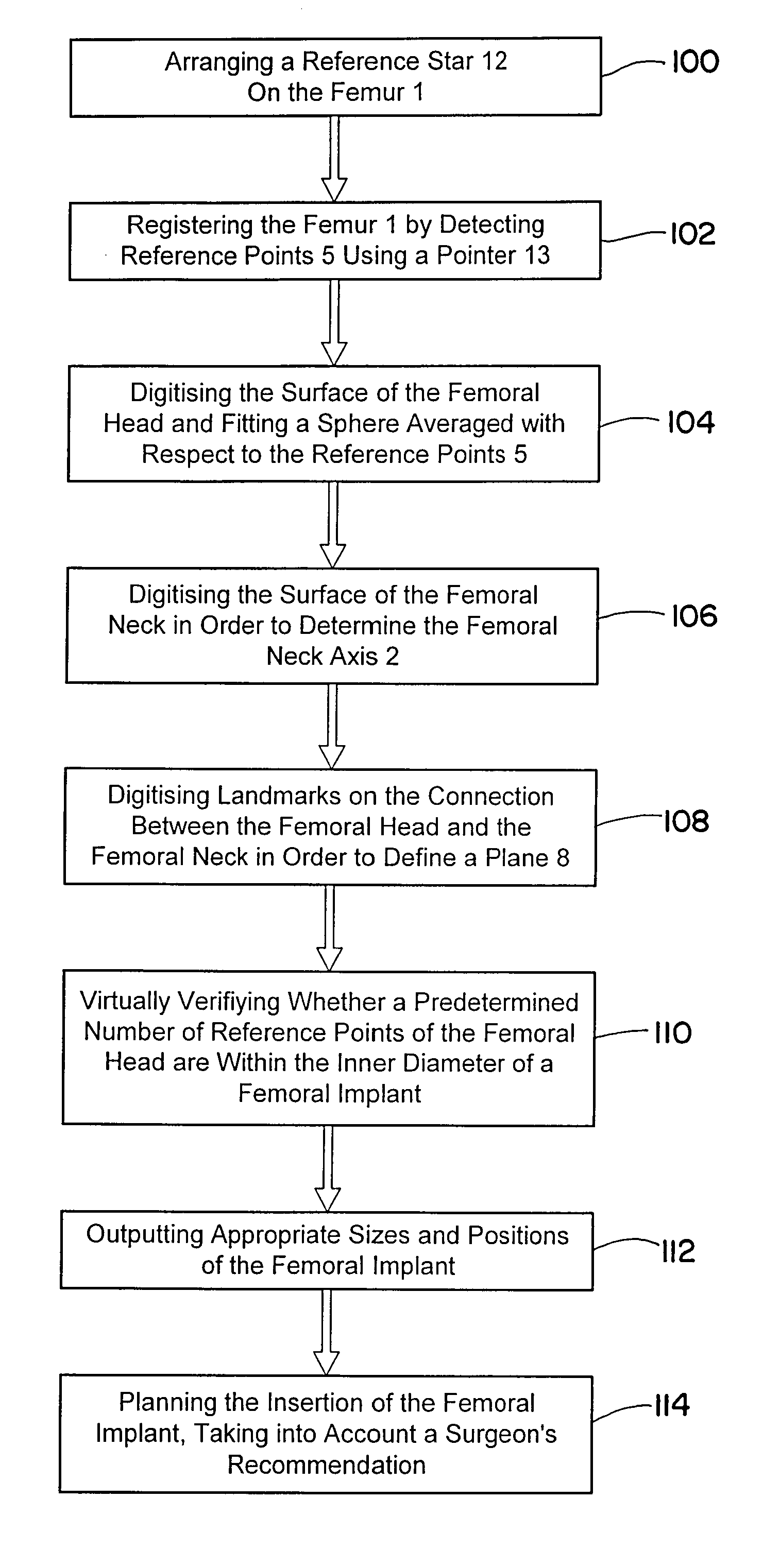
[0028]FIG. 1 shows a flow diagram of an exemplary method for ascertaining or selecting a femoral implant or a femoral head replacement or attachment from models of a femoral neck and / or a femoral head. With additional reference to FIG. 2, a reference star 12 that reflects or emits infrared radiation is arranged on the femur 1, as indicated at block 100. A position of the reference star 12 can be ascertained by an infrared camera 22 of a navigation system 20. By means of a pointer 13, the surface of a fraised-off femoral head 6 is scanned and reference points 5 of the femoral head 6 are detected by the camera 22 and provided to the navigation system 20, as indicated at block 102. The spatial position of the reference points can be ascertained by the navigation system 20 and, thus, the femur 1 can be registered.

[0029] By means of the ascertained reference points 5, the surface of the femoral head 6 also can be digitized by forming a virtual model of the femoral head 6, as indicated a...


PUM


Abstract

A method for selecting a femoral implant based on models of a femoral neck and / or a femoral head of a patient, includes: a) detecting reference points on the femoral neck and / or femoral head of the patient; b) registering the femoral neck and / or femoral head based on three-dimensional reference point spatial positions of the detected reference points; c) producing a femoral neck model and / or femoral head model from the three-dimensional reference point spatial positions; d) ascertaining a base size of a femoral implant model based on the femoral head model; e) producing a femoral implant model based on the base size of the femoral implant model; f) positioning the femoral implant model at a position in or on the femoral head model; g) ascertaining an implant value that indicates how many or what proportion of the ascertained reference point spatial positions are outside the femoral implant model; h) determining if the implant value exceeds a predetermined limit value; and i) if the implant value exceeds the limit value, repositioning the femoral implant model and performing steps g) to i), or if the implant value does not exceed the limit value, determining an appropriate size and position of the femoral implant.

Description

RELATED APPLICATION DATA [0001] This application claims priority of U.S. Provisional Application No. 60 / 806,504 filed on Jul. 3, 2006, which is incorporated herein by reference in its entirety.FIELD OF THE INVENTION [0002] The present invention relates generally to femoral implants and, more particularly, to a method and device for selecting a femoral implant for attachment to a femoral head during hip joint operations, wherein the femoral implant is selected based on virtual or digital models of a femoral neck and / or a femoral head of a patient. BACKGROUND OF THE INVENTION [0003] In hip joint operations the femoral neck is usually retained and the femoral head is fraised off. This enables a surface of a replacement femoral head or a femoral implant to be cemented onto or into the fraised femoral head. If a femoral implant is selected that is too small (e.g., an inner diameter of the implant is too small) and cemented on the fraised head, there exists the danger that the fraiser app...

Claims


Application Information

Patent Timeline
Patent Type & Authority Applications(United States)
IPC IPC(8): A61F2/36G09B23/28
CPCA61B19/50A61B19/52A61B19/5244A61B2017/00712A61B2019/502A61B2019/504A61F2002/4633A61B2019/508A61B2019/5255A61B2019/5268A61F2/36A61F2/3603A61F2/4657A61B2019/505A61B2034/102A61B2034/104A61B90/36A61B2034/2055A61B2034/2068A61B34/20A61B34/10A61B2034/105A61B2034/108
Inventor MUELLER, HEIKODICK, ROBERTADAMSKI, MARTINTUMA, GREGOR
Owner BRAINLAB
Learn More