Shaft Seal Device

a technology of shaft seal and seal lips, which is applied in the direction of engine seals, mechanical equipment, engine components, etc., can solve the problems of reducing the flexibility of choice, affecting the sealing effect, so as to achieve easy separation, increase the freedom of choice, and good adhesive

Inactive Publication Date: 2008-01-10
EAGLE INDS
View PDF8 Cites 4 Cited by
  • Summary
  • Abstract
  • Description
  • Claims
  • Application Information

AI Technical Summary

Benefits of technology

[0009] The shaft seal device related to the present invention is comprised of a seal portion and a reinforcement annulus wherein the seal portion has an annularly shaped engagement recess portion in which the engagement recess portion is in the form of a groove disposed in a close-fit engagement portion which is made of a rubber resilient material and the engagement recess portion has an opening in the side wall thereof opposite the sealed fluid and extends toward the sealed fluid side, wherein the reinforcement annulus further comprises a reinforcement portion and a support portion in which the reinforcement portion matingly fits the engagement recess portion (also referred to as an engagement groove) of the close-fit engagement portion in freely detachable a manner so as to provide a support for the close-fit engagement portion, in which the support portion provides a support for the hind surface of the seal lip. Therefore when the shaft seal device is to be scrapped after use, the seal portion made of rubber and the reinforcement annulus made of metal can easily be separated one another. This brings a merit that material-based separation and reprocessing of rubber and metal for recycling is made possible. In this assemblable shaft seal device, since rubber and metal are fabricated separately, a cleansing process and adhesion process which were required for the reinforcement annulus in conventional shaft seal devices can be omitted and an increased freedom of choosing less expensive rubber material with a good adhesiveness leads to a significant cost reduction thereof.
[0010] In addition, since there is disposed a seal sleeve wherein a first stopper is disposed in one axially end portion of the slide seal face so as to be able to abut the seal lip and a second stopper is disposed in the other axially end portion opposite the one end of the slide seal face so as to be able to abut the support portion and also a tight-fit engagement surface is disposed so as to be able to form a seal-tight contact with the rotary shaft, the seal sleeve can restrain the seal portion and the reinforcement annulus from coming loose after assembly of the seal portion and the reinforcement annulus. Therefore, as the assembly parts for the shaft seal device are maintained under an assembled state, a previous trouble for lack of assembly parts hampering assembly will be prevented. Also since the seal face of the seal lip is subjected to a slide movement against the slide seal face of the seal sleeve which is in a close-fit engagement with the rotary shaft, abrasion of the slide surface of the rotary shaft can be prevented, which is expensive and hard to be replaced. Further, since the slide seal face is disposed on the seal sleeve, it is possible to apply a precision finish thereto so as to make the slide seal face of a small area form a seal-tight contact with the seal face, thereby enhancing seal performance thereof as the result of prevention of abrasion in the slide seal face and the seal face.

Problems solved by technology

These impurities, in particular, which are caught on the seal faces cause abrasion of the rotary shaft.
The rotary shaft which is mounted in an apparatus is not straightforward to be replaced from the cost perspective.
While rubber-made seal lips or resin-made seal lips receive a high pressure from sealed fluid while making a secure contact with the rotary shaft, the slide seal faces of the rotary shaft and the seal lips will be worn out.
Therefore, an attempt to disintegrate the members based on different materials in order to recycle the members of a used shaft seal device is not a straightforward task because the baked integral structure of the reinforcement annulus and the seal lip makes a material-wise separation and recycling thereof difficult.
These two members, however, are hard to be separated from one another because they thermally stick to each other.
This process involves a lot of difficulties.
This parts management, however, is not straightforward because these two members are cluttered on the time of assembly.

Method used


Image

  • Shaft Seal Device
  • Shaft Seal Device
  • Shaft Seal Device

Examples


embodiment 1

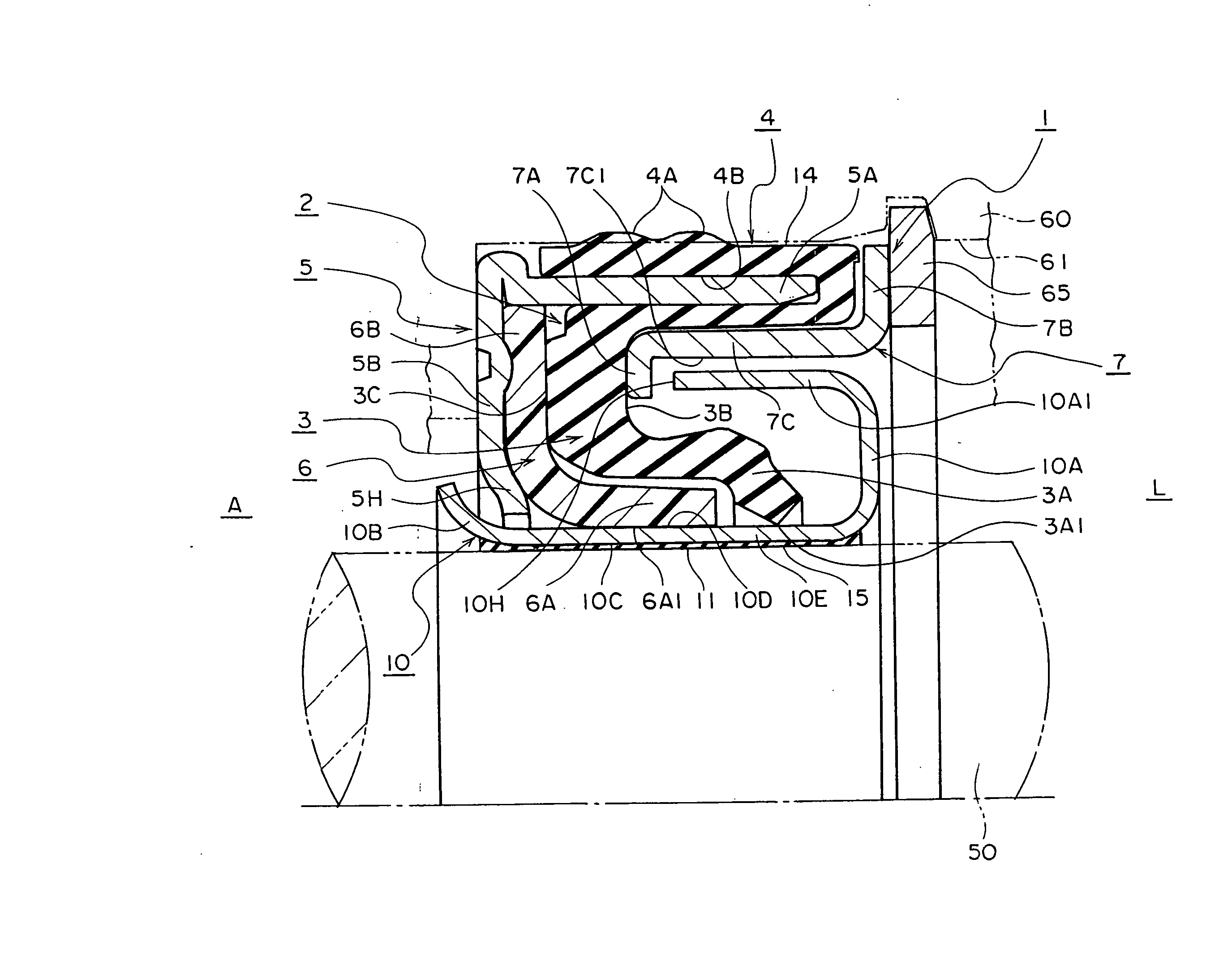
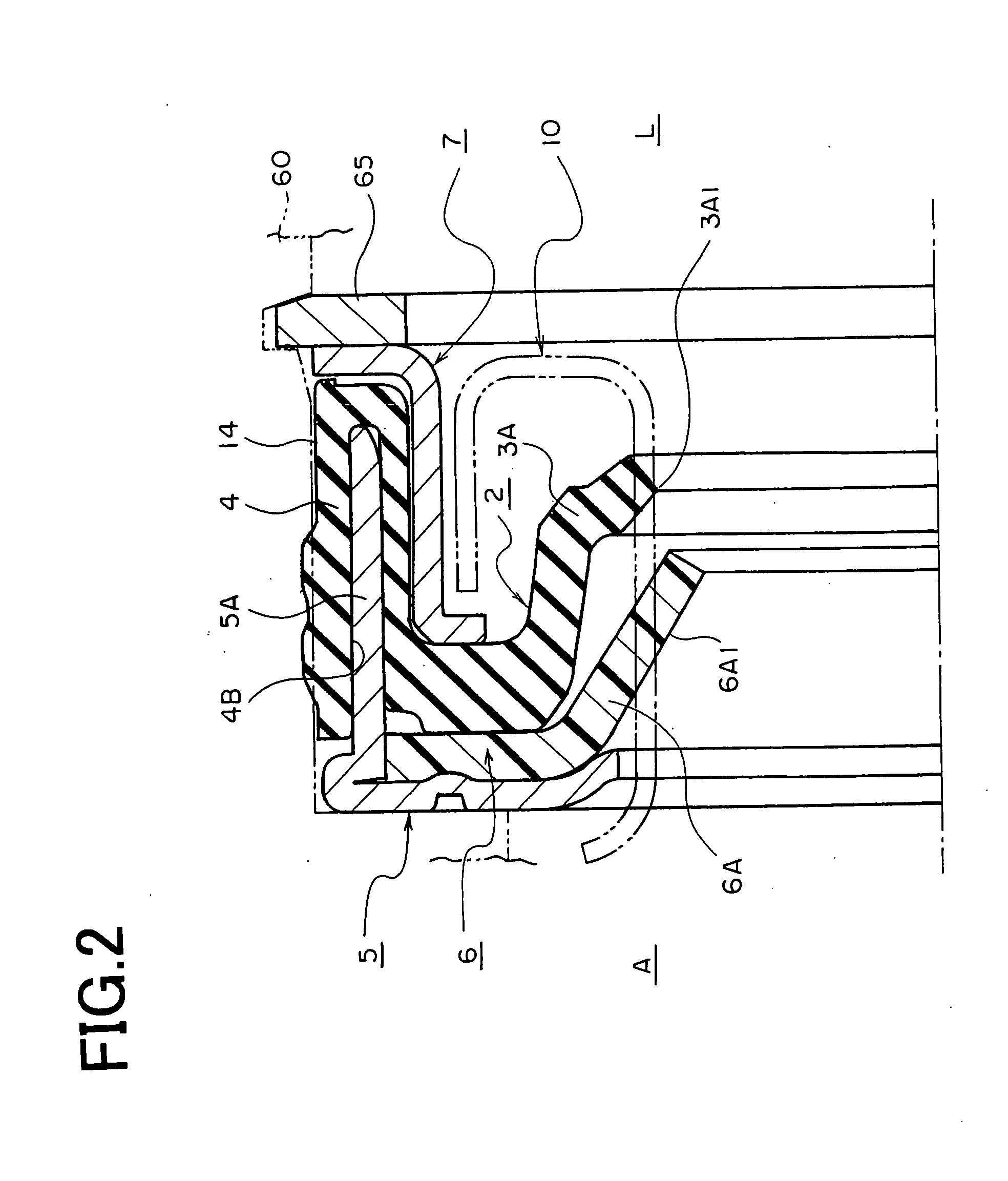
[0016] First, a shaft seal device of the embodiment 1 related to the present invention will be described. FIG. 1 shows a cross sectional view of a half portion of a shaft seal device 1. In FIG. 1, a rotary shaft 50 is mounted in a bearing bore 61 in a housing 60. A seal sleeve 10 fitted to the rotary shaft 50 is fabricated in a cylindrical form from a stainless steel sheet. Both ends of the seal sleeve 10 are bent radially outward. A first stopper 10A located in one of the inflected ends is bent to form L-shape cross section from the end and is structured so as to define U-shape cross section including a part of the distal end portion of the cylindrical portion 10E in a surrounding manner relative to an annular lip 3A. That is, the first stopper 10A extends from one end portion of the cylindrical portion 10E and defines a partitioning portion 10A1 in tubular design extending to the atmospheric A side so as to surround a first seal face 33A1 of the annular lip portion 3A. Preferably ...

embodiment 2

[0026] Next, a shaft seal device 1 of the embodiment 2 related to the present invention will be described. FIG. 3 is a cross sectional view of a half portion of the shaft seal device 1 related to the embodiment 2. What makes FIG. 3 different from FIG. 1 is that the urging portion 7A of the support annulus 7 is extended in L-shape so as to support the annular lip portion 3A such that the annular lip portion 3A does not expand radially outward. The end surface of the urging portion 7A is structured in a tooth form and fittingly mates with a stopper ring 8 which is made of rubber or resin material in detachable a manner. The stopper ring 8 can be brought to make a light contact with the inner circumferential surface 10M of the partitioning portion 10A1 so as to prevent impurities included in the sealed fluid from coming into the first seal face 3A1 side. Also the stopper ring 8 provides a support for restraining vibrations of the inner circumferential surface 10M during rotation. There...


PUM


Abstract

A shaft sealing device whose parts can be produced and assembled on a material-by-material basis to enable cost of the parts to be reduced and in which the parts can be disassembled on a material-by-material basis to enable the materials to be reused. A shaft sealing device (1) is composed of a seal section (2), a reinforcement ring (5), and a seal sleeve (10). The seal section (2) is made from a rubber-like elastic material and has a fitting section (4) sealingly fittable on a hole forming surface of a housing (60); a fitting recess section (4B) formed in a region that is from a side surface on the opposite side of to-be-sealed fluid (L) of the fitting section (4) to the to-be-sealed fluid (L) side; an annular seal lip (3) provided on the inner periphery of the fitting section (4); and a seal surface (3A1) provided inside the seal lip (3). The reinforcement ring (5) has a reinforcement section (5) removably fitted in the fitting recess section (4B) of the fitting section (4) and a support section (5B) for supporting the back side of the seal lip (3). The seal sleeve is made from metal or resin and has a sliding seal surface (10D) capable of sliding while in intimate contact with the seal surface (3A1); a first stopper (10A) capable of engaging with the seal lip (3), at one end of the sliding seal surface (10D); a second stopper (10B) capable of engaging with the support section (5B), at the other end, which is on the opposite side of the one end, of the sliding seal surface (10D); and an intimate contact fitting surface (15) sealingly fitting on a rotating shaft (50).

Description

TECHNICAL FIELD [0001] The present invention relates to a shaft seal device which tightly seals a sealed fluid residing in a clearance gap between a rotary shaft being mounted in a bore of the housing and the bore surface of the housing. More particularly, the invention relates to a shaft seal device in which assembly of a seal portion which is made of a rubber resilient material and a reinforcement annulus which provides the seal portion with a reinforcement is configured in a detachable manner, in which not only material based assembly of the members is made possible but also material based disassembly of the members is made possible for recycling of the materials, in which characteristics of the materials are well exhibited. BACKGROUND ART [0002] There are variety of shaft seal devices as a prior art related to the present invention. This shaft seal device is employed for providing a seal around a rotary shaft of water pump of automobiles or the like. Action fluid used in the wat...

Claims


Application Information

Patent Timeline
Patent Type & Authority Applications(United States)
IPC IPC(8): F16J15/32F16J15/328
CPCF16J15/3256F16J15/32
Inventor SANADA, MASAMITSU
Owner EAGLE INDS
Why Eureka
Try Eureka