
Surgical manipulator

a manipulator and surgical technology, applied in the field of surgical manipulators, can solve the problems of large impact on the space and support staff of the operating room, the size, weight and volume of the most current system, and the majority of current systems do not provide haptic feedback

Active Publication Date: 2007-12-27
MACDONALD DETTWILER & ASSOC INC
View PDF99 Cites 681 Cited by
  • Summary
  • Abstract
  • Description
  • Claims
  • Application Information

AI Technical Summary

Benefits of technology

[0019] The present invention provides embodiments of a surgical manipulator including a manipulator arm, an end-effector held by the manipulator arm, surgical too

Problems solved by technology

The overall size, weight and volume of most current systems are a major issue in that they have a major detrimental impact on operating room facility space and the support staff who set-up the equipment.
The majority of current systems do not provide Haptic feedback.
Manual surgical tool exchange increases the surgical operating time; increasing the time the patient is required to remain under anaesthesia and increasing facility costs.
However, the drawback of conventional servomotors presently in use in many surgical robots is their long axial length, so a right-angle transmission means is needed if excessive lateral extension of the manipulator arm joints is to be avoided.
Of all the available right-angle transmission components at present, bevel gear pairs deliver high torque and backdrivability, but backlash is typically high and they seldom come in small packages.
The traditional standard bevel gear box has large backlash in transmission which is highly undesirable in applications where high precision is required in both directions of motion.
Worm gear boxes can have low-backlash configurations but its indirect proportional relationship between the efficiency versus the gear ratio leads to a bulkier and heavier overall unit, while also the lack of back-drivability is also undesirable in the event of crash recovery or calibration common to robotics applications.
Unfortunately, the mechanism does not allow for a right-angle drive version.
No commercially available right-angle transmission in the market currently has both zero-backlash and high efficiency capabilities in a compact in-line package.

Method used


Image

  • Surgical manipulator
  • Surgical manipulator
  • Surgical manipulator

Examples


Embodiment Construction

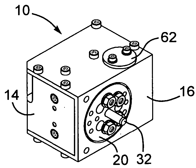
[0156] Generally speaking, the systems described herein are directed to a surgical manipulator apparatus. As required, embodiments of the present invention are disclosed herein. However, the disclosed embodiments are merely exemplary, and it should be understood that the invention may be embodied in many various and alternative forms. The Figures are not to scale and some features may be exaggerated or minimized to show details of particular elements while related elements may have been eliminated to prevent obscuring novel aspects. Therefore, specific structural and functional details disclosed herein are not to be interpreted as limiting but merely as a basis for the claims and as a representative basis for teaching one skilled in the art to variously employ the present invention. For purposes of teaching and not limitation, the illustrated embodiments are directed to a surgical manipulator apparatus.

[0157] The surgical manipulator apparatus comprises a multi-jointed robotic arm,...


PUM


Abstract

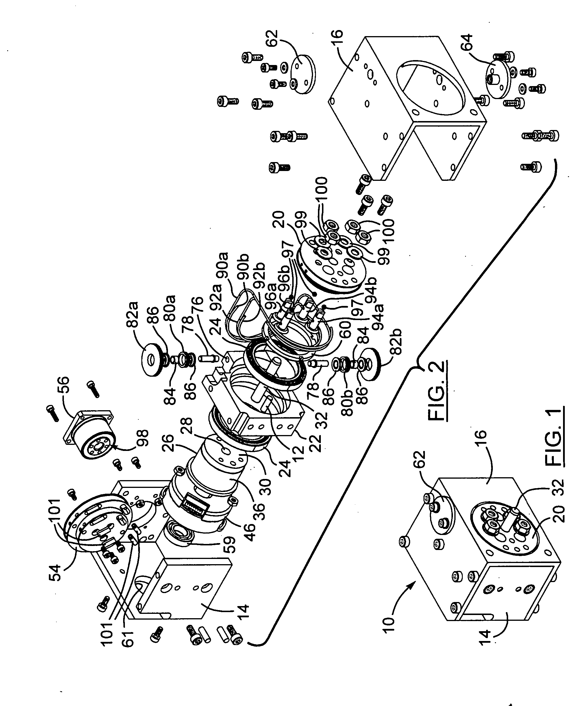
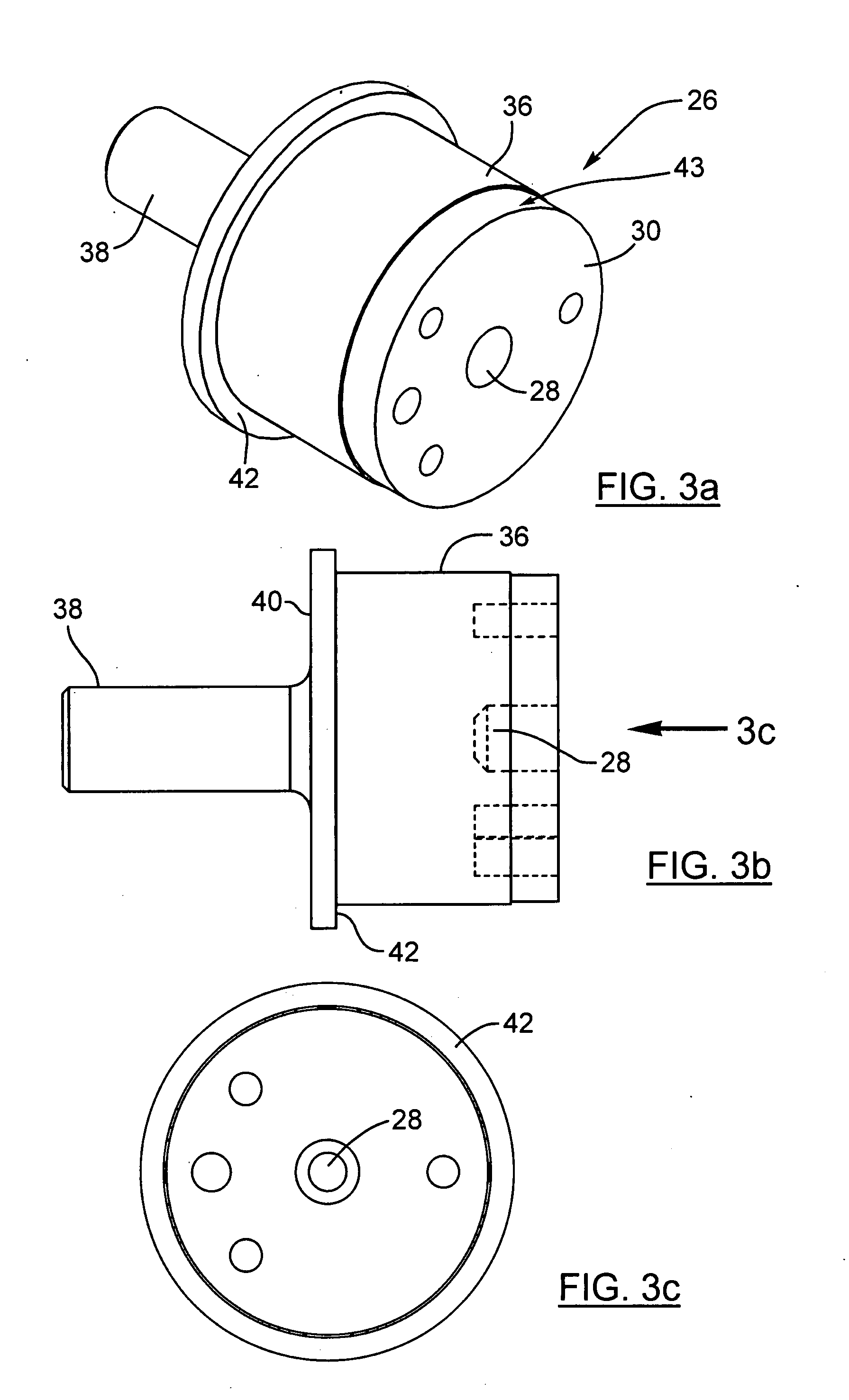
The present invention provides a surgical manipulator including a manipulator arm, an end-effector held by the robotic arm, surgical tools held by the end-effector and manipulator joints, particularly right-angle drive devices for transmitting rotational motion in one axis to a perpendicular axis.

Description

CROSS REFERENCE TO RELATED U.S. PATENT APPLICATIONS [0001] This patent application relates to U.S. utility patent application Ser. No. 60 / 813,353 filed on Jun. 14, 2006 entitled SURGICAL MANIPULATOR, filed in English, which is incorporated herein in its entirety by reference.FIELD OF THE INVENTION [0002] The present invention relates to a surgical manipulator including a manipulator arm, an end-effector held by the manipulator arm, surgical tools held by the end-effector and manipulator joints, particularly right-angle drive devices for transmitting rotational motion in one axis to a perpendicular axis. BACKGROUND OF THE INVENTION [0003] The goal of surgical manipulator systems is to apply robotic and sensor technologies to improve the quality of patient surgical outcomes in a cost-effective manner. Surgical robotics can attain this goal through repeatable increased spatial resolution and better geometric accuracy of surgical tools positioning by the surgeon, faster operating speed,...

Claims


Application Information

Patent Timeline
IPC IPC(8): A61B19/00A61B46/23
CPCA61B19/081A61B19/2203A61B19/5212A61B2019/2223B25J9/104A61B2019/2242A61B2019/2246A61B2019/2296B25J9/047A61B2019/2234A61B2034/715A61B34/71A61B90/361A61B34/30A61B46/10A61B34/37A61B2034/305A61B34/77A61B46/23B25J13/00F16D3/00
Inventor YEUNG, BENNY HON BUNGREGORIS, DENNISBEDNARZ, BRONISLAWGRAY, MICHAEL A.
Owner MACDONALD DETTWILER & ASSOC INC
Learn More