
Wound Irrigation Device

a technology for wounds and irrigation devices, applied in the field of wound irrigation devices, can solve the problems of device not addressing various factors concerning patients, difficult use, and cumbersome wound irrigation devices, and achieve the effect of convenient removal of fluids and high efficacy

Inactive Publication Date: 2007-12-27
INNOVATIVE THERAPIES INC
View PDF99 Cites 26 Cited by
  • Summary
  • Abstract
  • Description
  • Claims
  • Application Information

AI Technical Summary

Benefits of technology

"The invention is a wound irrigation system that uses an electromechanical vacuum apparatus to create a therapeutic vacuum. The system includes a microprocessor-based device that controls the vacuum pump and can maintain a desired level of vacuum pressure. The system also includes a canister, dressing, and irrigation vessel for communicating vacuum pressure to the wound. The system can be used in a portable and battery-powered manner. The patent also describes a method for improving the generation and control of the therapeutic vacuum, which involves monitoring pressure signals from sensors and using a control algorithm to maintain the desired level of vacuum pressure. The patent also mentions the use of various materials for the dressing, which can be porous and have mechanical properties that promote wound healing. The technical effects of the invention include improved wound irrigation and drainage, reduced mechanical noise, and the ability to create a therapeutic vacuum for wound healing."

Problems solved by technology

In addition to using negative pressure wound therapy, many devices employ concomitant wound irrigation.
The wound irrigation apparatus, although able to provide efficacious therapy, is somewhat cumbersome, difficult to use, and generally impractical.
Such a device does not address various factors concerning patients, specifically ease of use, portability and the ability to provide therapy with a minimum amount of unwanted mechanical noise.
Such devices also fail to address portability, ease of use and noise reduction.

Method used


Image

  • Wound Irrigation Device
  • Wound Irrigation Device
  • Wound Irrigation Device

Examples


Embodiment Construction

[0018] Although those of ordinary skill in the art will readily recognize many alternative embodiments, especially in light of the illustrations provided herein, this detailed description is of an embodiment of the invention, the scope of which is defined only by the claims appended hereto.

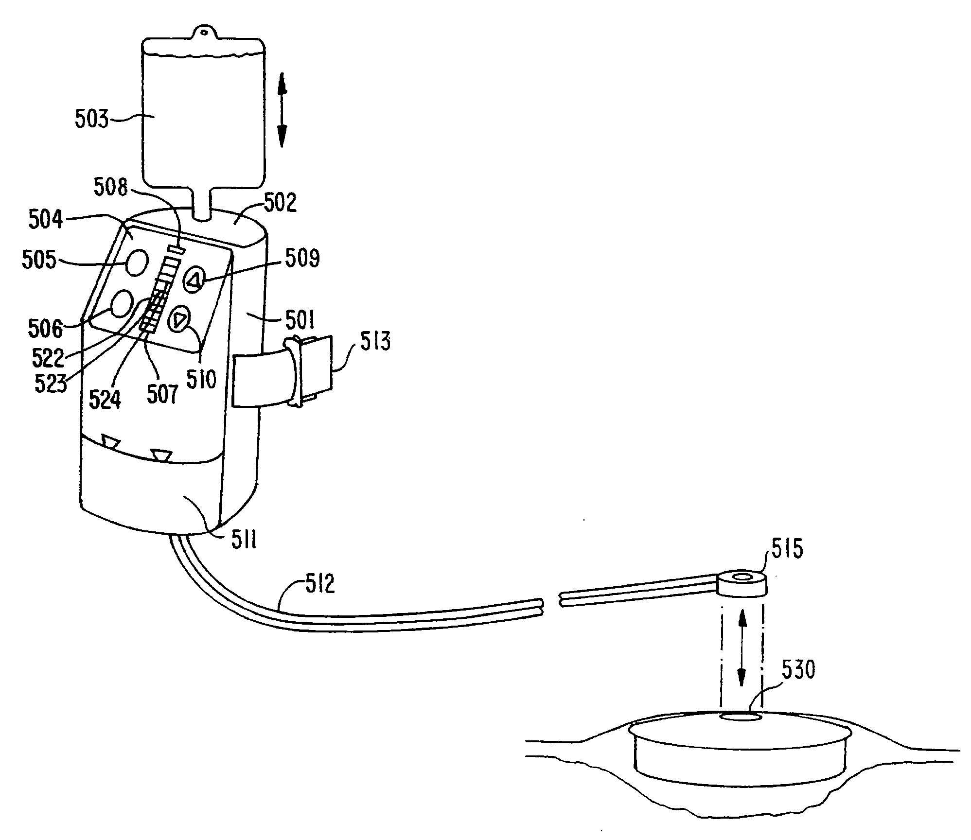
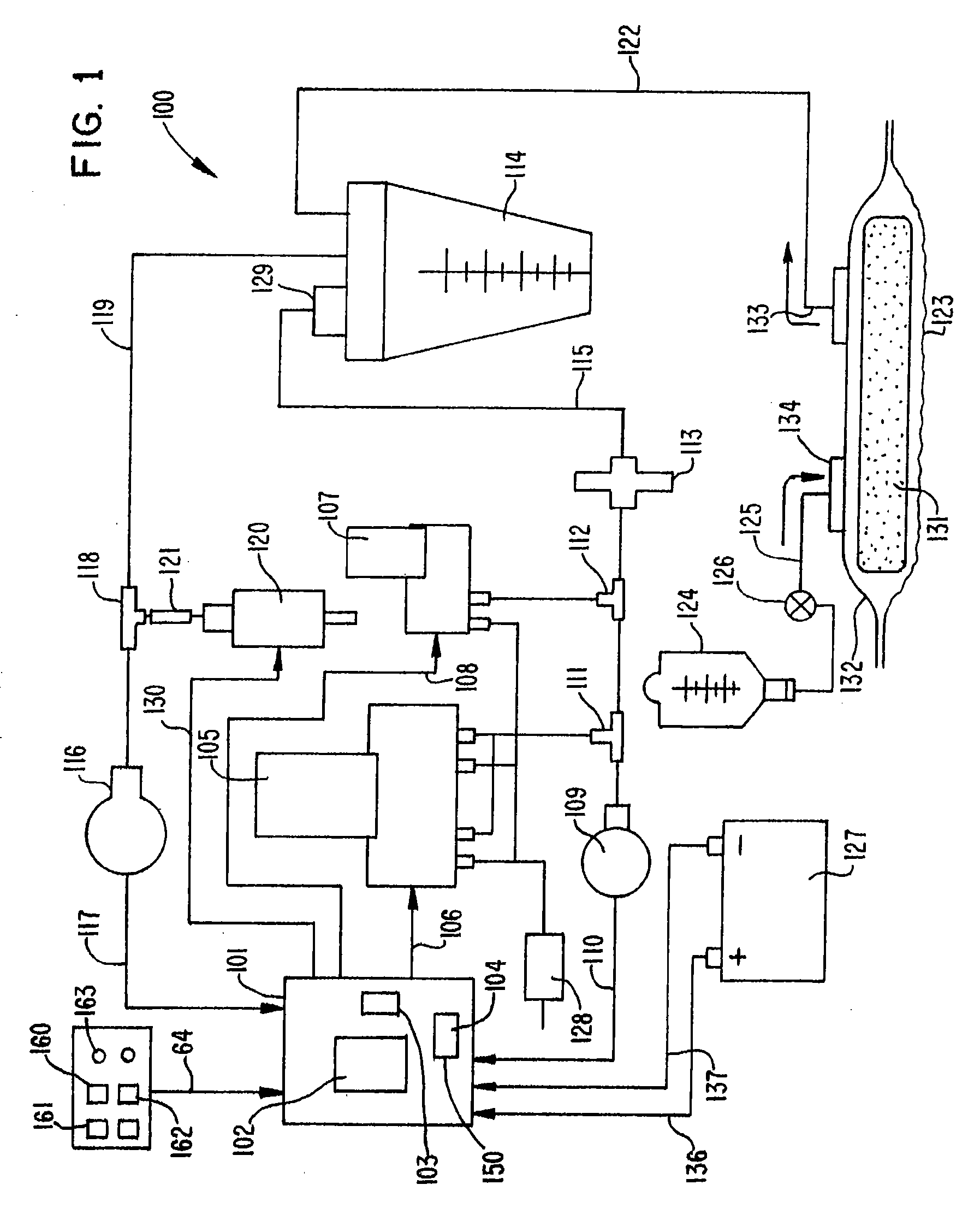
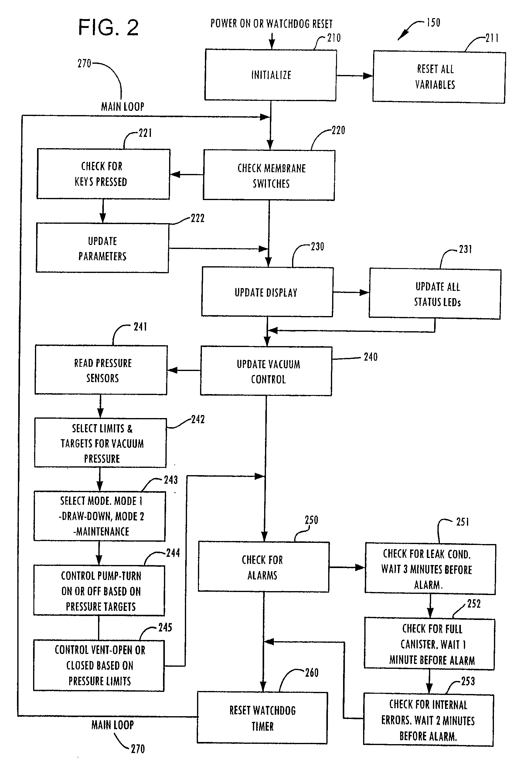
[0019] As illustrated in FIG. 1, a wound irrigation and vacuum drainage system is referred to by the numeral 100 and generally includes a microcontroller 101 having an embedded microprocessor 102, Random Access Memory (RAM) 103 and Read Only Memory (ROM) 104. ROM 104 contains the programming instructions for a control algorithm 150 (see FIG. 2). ROM 104 is non-volatile and retains its programming when the power is terminated. RAM 103 is utilized by the control algorithm for storing variables such as pressure measurements, alarm counts and the like, which the control algorithm 150 uses while generating and maintaining the vacuum. A membrane keypad and display 160 is electrically associated with mi...


PUM


Abstract

An apparatus includes a fluid permeable dressing and a cover membrane configured to extend over the fluid permeable dressing. A tube is coupled to the fluid permeable dressing and is configured to apply suction through the fluid permeable dressing. A fluid reservoir is coupled to the cover membrane, the fluid vessel including an inlet port configured to receive a fluid and an outlet port fluidically coupled to the fluid permeable dressing.

Description

CROSS REFERENCE TO RELATED APPLICATION [0001] This application is a divisional of U.S. patent application Ser. No. 11 / 237,880, entitled “Wound Irrigation Device,” filed on Sep. 29, 2005, which is a continuation of U.S. patent application Ser. No. 11 / 198,148, entitled “Wound Irrigation Device,” filed Aug. 8, 2005; each of which is hereby incorporated by reference in its entirety.BACKGROUND [0002] The invention is generally directed to a method and apparatus for the promotion of wound healing. More particularly, the present invention relates to providing fluid irrigation and vacuum drainage of a wound. Negative pressure wound therapy, also known as vacuum drainage or closed- suction drainage is known. A vacuum source is connected to a semi-occluded or occluded wound dressing. Various porous dressings comprising gauze, felts, foams, beads and / or fibers can be used in conjunction with an occlusive semi-permeable cover and a controlled vacuum source. [0003] In addition to using negative ...

Claims


Application Information

Patent Timeline
Patent Type & Authority Applications(United States)
IPC IPC(8): A61F13/40
CPCA61F13/02A61F2013/00536A61F2013/0054A61M1/0031A61M1/0049A61M2205/15A61M1/0088A61M2205/3317A61M2205/3344A61M2205/42A61M2209/088A61M1/0058A61F13/0226A61M1/782A61M1/784A61M1/882A61M1/982A61M1/96A61M1/915A61M1/92A61M1/984A61F13/05A61M1/74
Inventor VOGEL, RICHARD C.
Owner INNOVATIVE THERAPIES INC
Learn More