
Clock offset compensator

a compensator and clock technology, applied in the field of clock compensation, can solve the problems of increasing the cost of the device, reducing so as to achieve the effect of improving the accuracy of the devi

Active Publication Date: 2007-12-27
MARVELL ASIA PTE LTD
View PDF4 Cites 20 Cited by
  • Summary
  • Abstract
  • Description
  • Claims
  • Application Information

AI Technical Summary

Benefits of technology

This solution enables the use of less expensive local clock generators while ensuring data transmission standards are met, reducing device costs without compromising performance.

Problems solved by technology

Ceramic resonators are cheaper than crystal resonators but not as accurate.
When the device is implemented using lower accuracy clock generators, the transmitted data from the device to the host may not meet data transmission standards, such as SATA or other standards.
As a result, the device must be implemented with a more expensive local clock generator with improved accuracy, which increases the cost of the device.

Method used


Image

  • Clock offset compensator
  • Clock offset compensator
  • Clock offset compensator

Examples


Embodiment Construction

[0025] The following description of the preferred embodiment(s) is merely exemplary in nature and is in no way intended to limit the invention, its application, or uses. For purposes of clarity, the same reference numbers will be used in the drawings to identify similar elements.

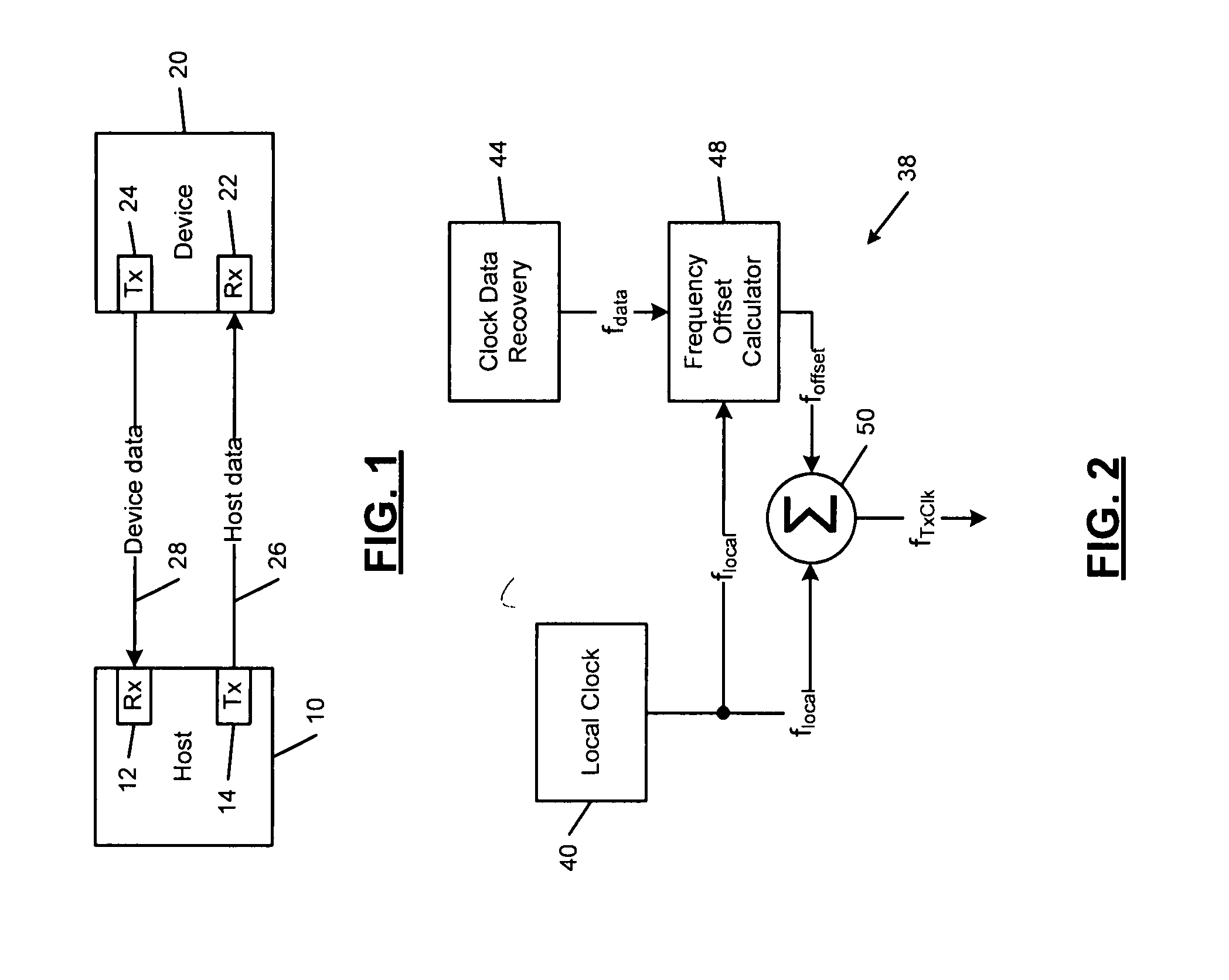
[0026] Referring now to FIG. 1, a host 10 includes a receiver 12 and a transmitter 14. A device 20 includes a receiver 22 and a transmitter 24. The transmitter 14 of the host 10 transmits host data 26 to the receiver 22 of the device 20. The transmitter 24 of the device 20 transmits device data 28 to the receiver 12 of the host 10.

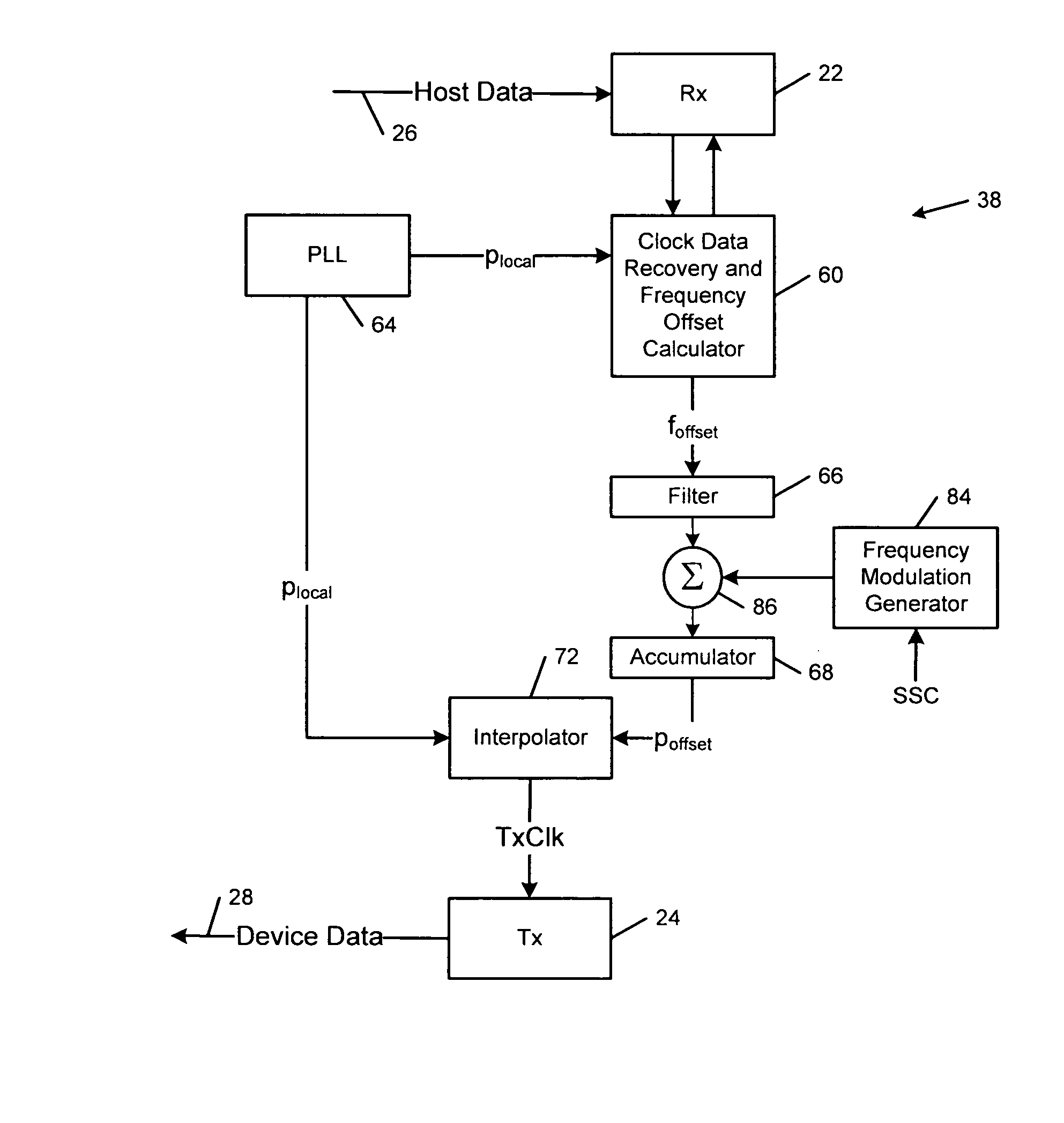
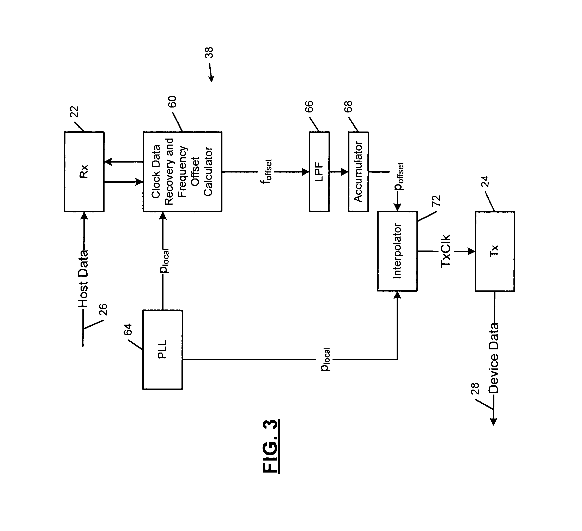
[0027] Referring now to FIG. 2, the device 20 includes a frequency offset compensator generally identified at 38. A local clock generator 40 generates a local clock frequency fhd local. The device 20 also includes a clock data recovery circuit 44 that determines a clock frequency fdata of the host 10 from data transmitted by the host 10. A frequency offset calculator 48 compares ...


PUM


Abstract

A device comprises a transmitter, a receiver and a clock generator that generates a local clock frequency. A clock recovery circuit communicates with the receiver and recovers a host clock frequency from data received from a host by the receiver. A frequency offset circuit communicates with the clock recovery circuit and the clock generator and generates a frequency offset based on the clock frequency and the recovered host clock frequency. A frequency compensator compensates a frequency of the transmitter using the frequency offset.

Description

CROSS-REFERENCE TO RELATED APPLICATIONS [0001] This application is a continuation of U.S. patent application Ser. No. 10 / 267,177 filed on Oct. 9, 2002. The disclosure of the above application is incorporated herein by reference.FIELD OF THE INVENTION [0002] The present invention relates to clock compensation, and more particularly to compensating a local clock of a device that receives data from a host for frequency offset when transmitting data from the device to the host. BACKGROUND OF THE INVENTION [0003] A host and a device typically transmit and receive data to and from each other. For example in a personal computer environment, a disk drive controller (host) is often connected to a disk drive (device). The host is typically implemented using a relatively accurate host clock generator. The accuracy is often required to meet the specifications of a host processor and / or other host components. [0004] The host and the device may be connected using a Serial Advanced Technology Atta...

Claims


Application Information

Patent Timeline
Patent Type & Authority Applications(United States)
IPC IPC(8): H03D3/24H03L7/081H03L7/197H04L7/033
CPCH03L7/081H04L7/0337H03L7/197G06F1/10
Inventor SUTIOSO, HENRIWU, LEI
Owner MARVELL ASIA PTE LTD
Learn More