Mechanical Seal Device
- Summary
- Abstract
- Description
- Claims
- Application Information
AI Technical Summary
Benefits of technology
Problems solved by technology
Method used
Image
Examples
example 1
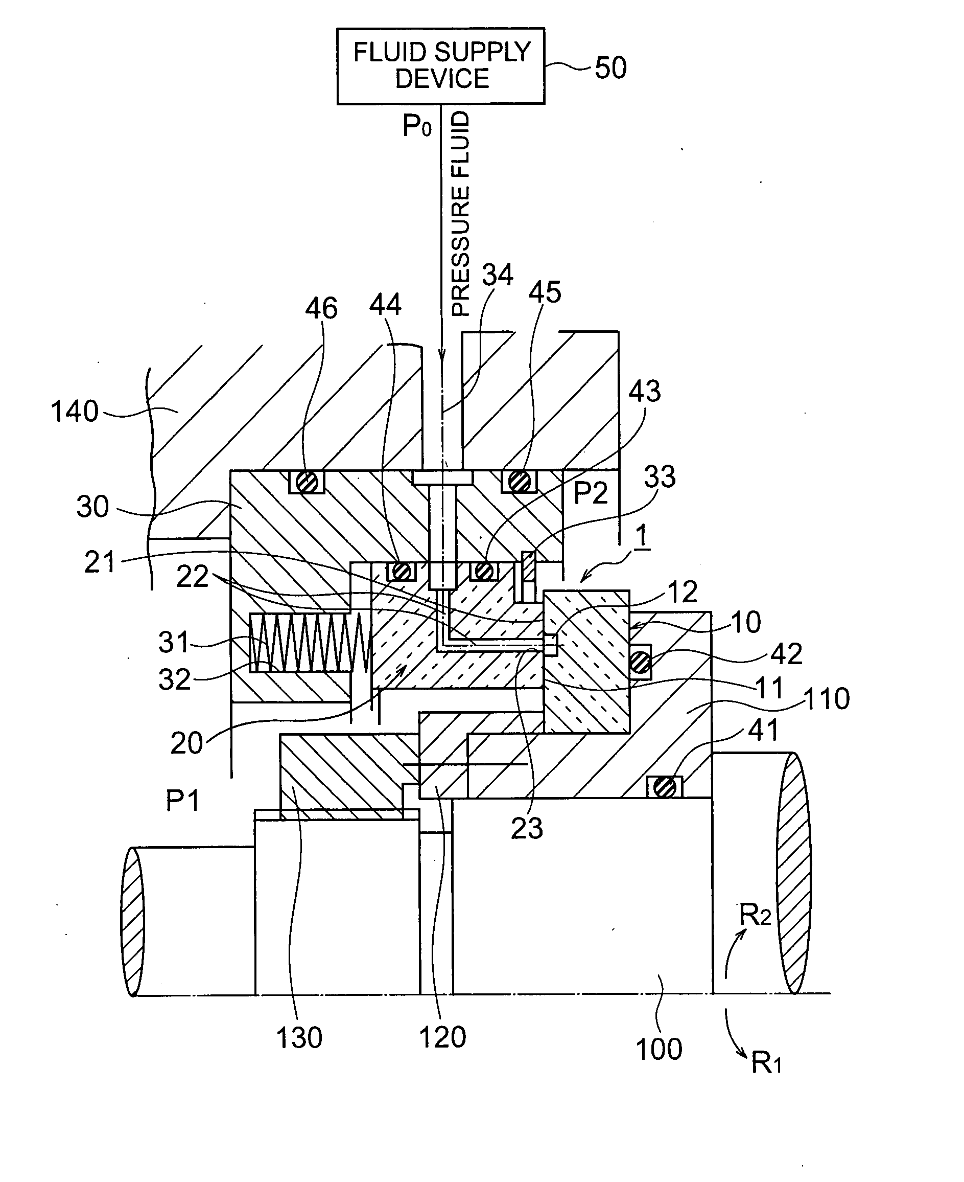
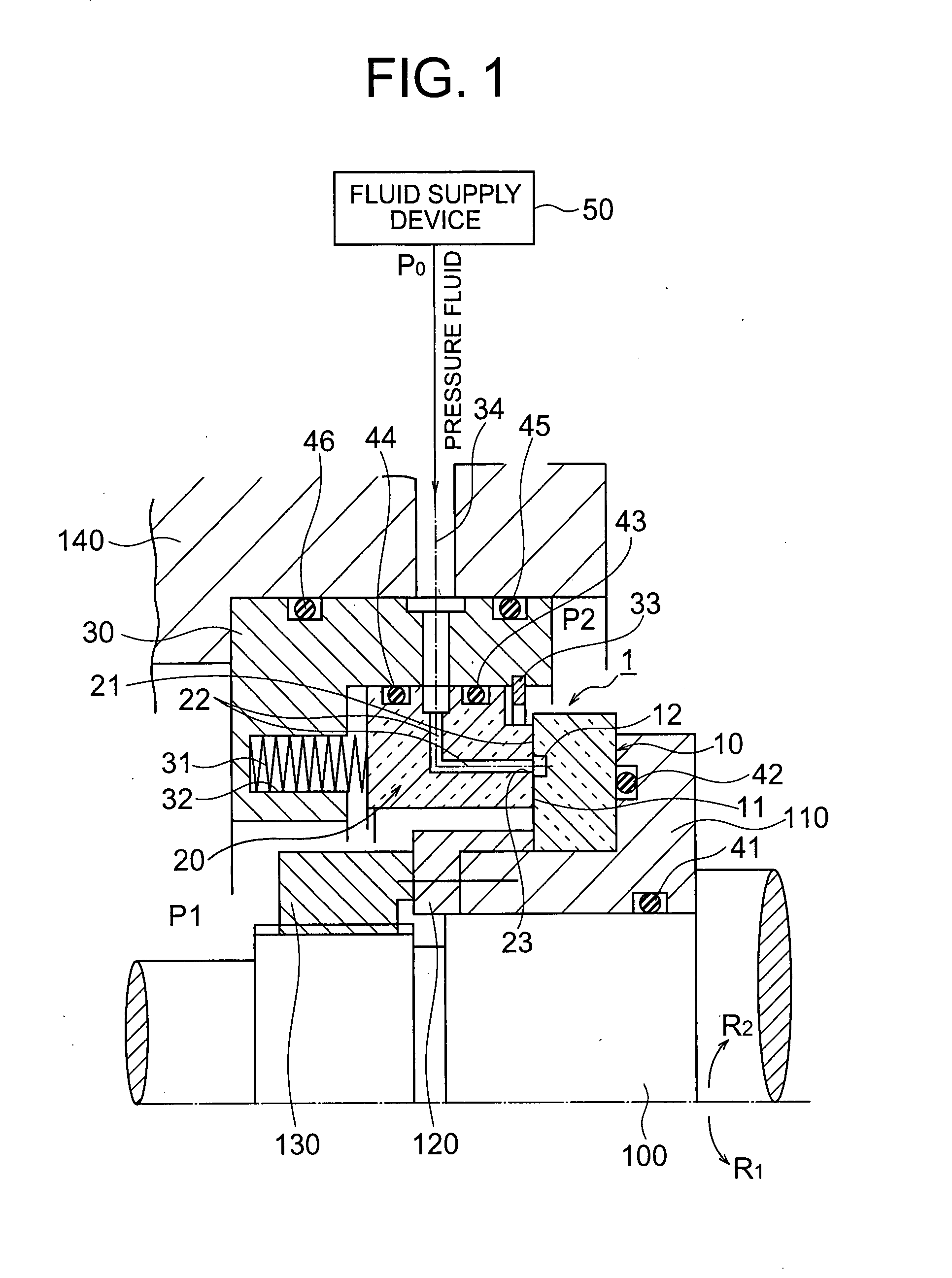
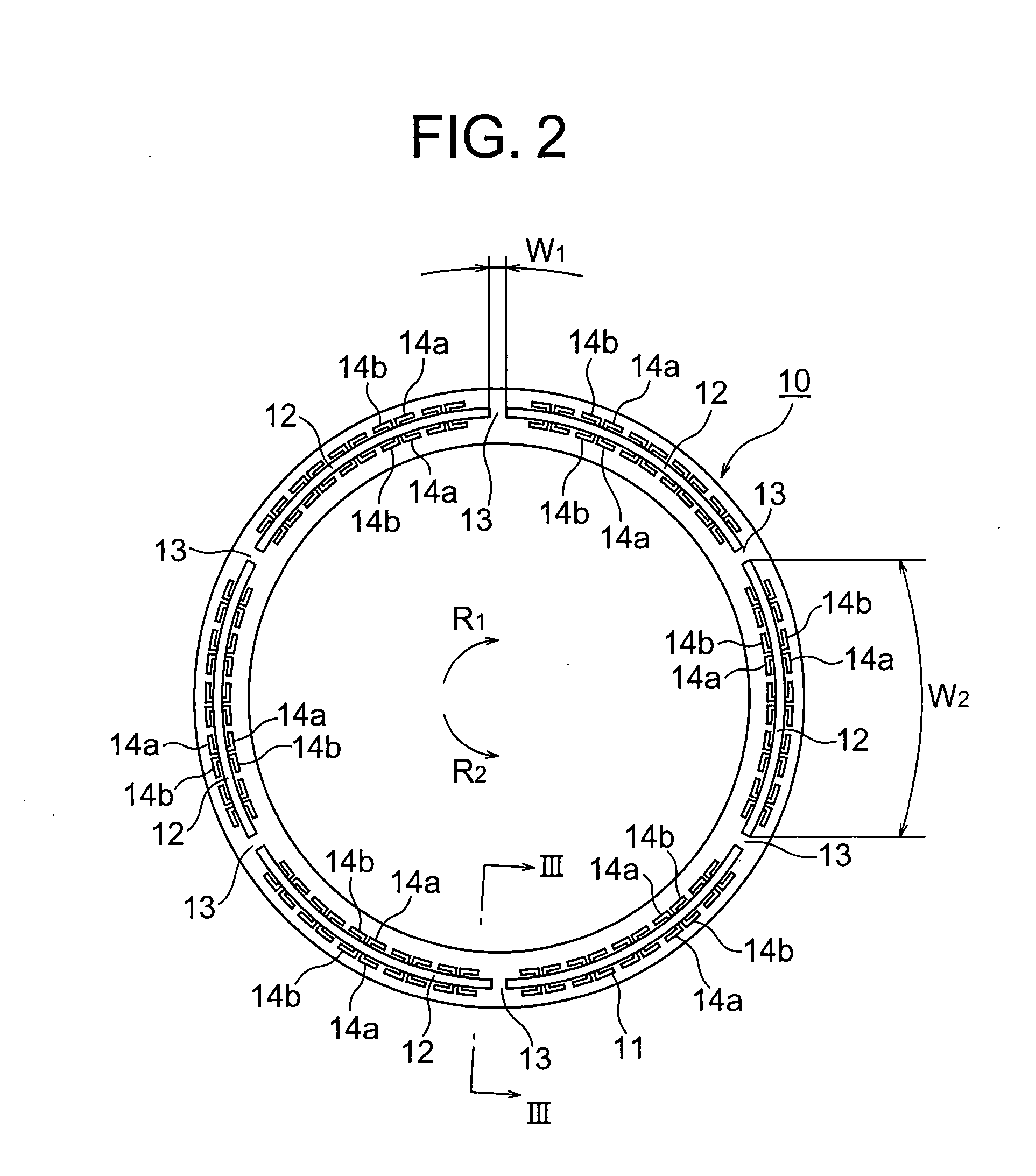
[0133] As a mechanical seal device of an example 1, a rotational seal ring having arc-shaped grooves formed thereon and a stationary seal ring having circular-shaped outlet portions formed thereon were used to produce a mechanical seal device configured as explained in the first embodiment. In the example 1, a depth t1 of the arc-shaped grooves was 1 mm, a circumferential direction length W2 of the arc-shaped grooves was 112 mm, a circumferential direction length W1 of the partition walls was 4 mm and a circumferential direction length W3 of the outlet portions was 2 mm. A production condition of the mechanical seal device produced in the example 1 is shown in Table 1.
[0134] [Table 1]
TABLE 1Partition WallArc-shaped GrooveCutOutlet PortionDepthCDL*CDL*AmountDepthCDL*Formedt1W2W1Cut ort1−t0Formedt2W3or Not[mm][mm][mm]Not[mm]or Not[mm][mm]Example 1Yes11124No—No—2Example 2Yes11124Yes0.07No—2Example 3Yes0.051124No—Yes0.515.4ComparativeNo———No—Yes0.25112Example
*CDL = Circumferential Dire...
example 2
[0137] As a mechanical seal device of an example 2, a rotational seal ring having arc-shaped grooves formed thereon and low partition walls and a stationary seal ring having arc-shaped outlet portions formed thereon were used to produce a mechanical seal device configured as explained in the seventh embodiment. In the example 2, a depth t1 of the arc-shaped grooves was 1 mm, a circumferential direction length W2 of the arc-shaped grooves was 112 mm, a circumferential direction length W1 of the partition walls was 4 mm, a cutting amount (t1−t0) at upper parts of the partition walls was 0.07 mm and a circumferential direction length W3 of the outlet portions was 2 mm. A production condition of the mechanical seal device produced in the example 2 is shown in Table 1. Vibration evaluation was made on the mechanical seal device of the example 2 under conditions of 31 patterns in the same way as in the example 1. FIG. 20 is a graph showing a result of the vibration evaluation of the mecha...
example 3
[0138] As a mechanical seal device of an example 3, a rotational seal ring having arc-shaped grooves formed thereon and a stationary seal ring having arc-shaped outlet portions formed thereon were used to produce a mechanical seal device configured as explained in the eighth embodiment. In the mechanical seal device of the example 3, a depth t1 of the arc-shaped grooves was 0.05 mm, a circumferential direction length W2 of the arc-shaped grooves was 112 mm, a circumferential direction length W1 of the partition walls was 4 mm, a depth t2 of the outlet portions was 0.5 mm and a circumferential direction length W3 of the outlet portions was 15.4 mm. A production condition of the mechanical seal device produced in the example 3 is shown in Table 1. Vibration evaluation was made on the mechanical seal device of the example 3 under conditions of 28 patterns in the same way as in the example 1. FIG. 21 is a graph showing a result of the vibration evaluation of the mechanical seal device i...
PUM
 Abstract
Description
Claims
Application Information
 - R&D
- Intellectual Property
- Life Sciences
- Materials
- Tech Scout
- Unparalleled Data Quality
- Higher Quality Content
- 60% Fewer Hallucinations
Browse by: Latest US Patents, China's latest patents, Technical Efficacy Thesaurus, Application Domain, Technology Topic, Popular Technical Reports.
© 2025 PatSnap. All rights reserved.Legal|Privacy policy|Modern Slavery Act Transparency Statement|Sitemap|About US| Contact US: help@patsnap.com


