[0046] To aid in understanding, previous disclosure in Pending Parent patent applications is repeated herein, with some amendment, to provide insight as to systems to which the present invention can be applied. One such
system is a local filter comprising a combination manifold and single lever cantered element system to which a filter module removably attaches. A ¼ rotation of the single lever mediates simultaneous operation of both valving and filter module release, and facilitates changing removably attachable filter modules without the need for tools. A second thereof is a floor mountable whole house water filter which does not develop significant
back pressure in use because water enters via a perforated tube inlet, then flows down said perforated tube and exits radially outward through
activated carbon or a
ceramic filter toward a larger area, before exiting via an output port in an outer housing thereof. And the third thereof is another floor mountable system which is designed to allow entering of a mixture of non-water component(s), (eg. oil), and water thereinto and which develops a high
back pressure, and via causing said mixture to pass through a mixture of
polypropylene and plastic beads in an upper approximately ⅔ thereof, and
polypropylene in the lower approximately ⅓ thereof, providing water at an outlet from which the non-water component(s) has been removed. It is to be understood that while preferred locations for the
ceramic with anti-microbial embedded therewithin, and granular
activated charcoal in said systems, will be pointed out, said ceramic with anti-microbial embedded therewithin, and granular activated
charcoal can be placed at any functional locations therein. Local Filter
[0059] The filter module preferably comprises, as viewed in side elevation, receptors in an outer covering thereof which have a vertical and a horizontal section such that each forms an “L” shape. Said filter module then further comprises a filter lid which attaches to said filter module outer covering by way of sliding nibs on said filter lid into the vertical portions of said receptors on said filter module outer covering, and then causing a slight rotation motion of filter lid so that nibs are positioned in the horizontal portions of said
receptor portions. In use rotating said filter lid so that said nibs thereon are in the vertical sections of the receptors in the filter module outer covering allows entering and removing the filter lid, and rotating said filter lid so that the nibs are in the horizontal portions of the “L” shaped receptors secures said lid in place in the filter module.
[0079] g4) positioning said filter lid such that nibs thereon align with vertical portions of the receptors in said filter module outer covering and causing said filter lid to move toward said filter module outer covering in a direction defined by the locus of said vertical portions of said receptors;
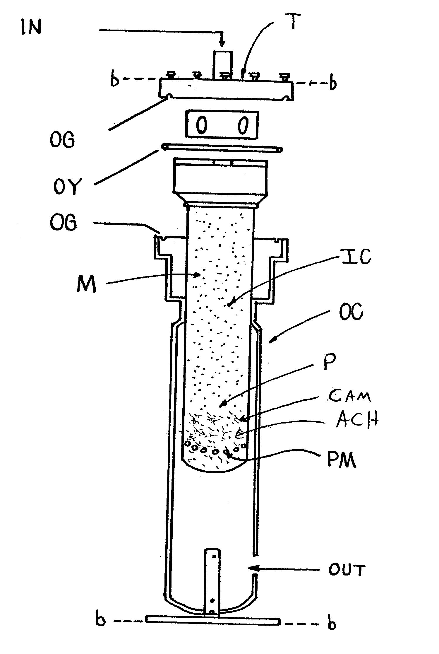
[0081] Continuing, in more detail, Pending application Ser. No. 11 / 452,013 Filed Jun. 14, 2006 discloses a system comprising a floor mountable whole house water filter which because of its design does not develop significant
back pressure to water entered thereinto. This is because
water flow is completely or at least predominately outward through filtering means, from a small area toward a large area. To achieve this result, the said invention system can comprise a housing with an inner colander that is slotted, and have a
bag filter which contains filler material, or a ceramic filter, fitted into said slotted inner colander. A perforated tube that is capped on the bottom end is centered in the
bag filter, and
activated carbon is caused to be present in said
bag filter with the centered perforated tube positioned in the center thereof. Said perforated tube serves to distribute water input thereto into the filter
activated carbon along the length thereof. With a bag filter full of activated carbon or a ceramic filter in place, a
top cap with centering tube is placed over the slotted colander and the center tube
top cap is then secured thereto. The slotted colander is lowered into the filter housing, and the
filter element seals against an “O”-ring that is present around the outside of slotted colander in a groove designed therefore. The “O”-ring is located near the top of the colander and seals the colander /
filter element against the filter housing to prevent water migration around the
filter element to the
discharge. Water enters the top of the filter element via the perforated tube, and said inlet water flows down the perforated tube, and exits therefrom radially outward through the activated carbon, then out of the bag filter through the slotted colander to
discharge of the filter outer housing. As mentioned, this design results in next to no
water pressure drop through the described filter, utilization of the entire carbon
bed, and easy change out of the filter element when required. The user then, never comes in contact with the captured
hazardous waste.
[0085] Continuing, the ceramic filter is cast to fit inside the slotted colander, the top of the ceramic filter is sealed to the slotted colander preventing non-filtered water migrating around the ceramic filter to
discharge. The cast ceramic filter is fitted into the slotted colander a perforated tube that is capped on the bottom end is then centered in the ceramic filter, activated carbon is caused to be present in the ceramic filter with the centered perforated tube positioned in the center. With the ceramic filter full of activated carbon a
top cap with centering tube is placed over the slotted colander and center tube this top cap is then secured to the slotted colander. The slotted colander is lowered into the filter housing placing the filter element against a sealing “O”-ring that is installed around the outside of slotted colander in a groove designed to receive the “O”-ring, which is located near the top of the colander. This seals the colander / filter element against the filter housing and prevents water migration around the filter element to discharge. Water enters the top of the filter element via the perforated tube inlet water flows down the perforated tube and exits radially outward, proceeds through the activated carbon and ceramic filter, then through the slotted colander to discharge of the filter housing. This design results in next to no
water pressure drop through the said invention filter, and utilization of a
single element carbon
bed and ceramic filter enables easy change out of the filter element when required. Further, as mentioned, the user never comes in contact with the captured
hazardous waste.
[0089] The bag or ceramic filter is preferably an easily changed one piece system, and where a ceramic filter is used it can have silver embedded in the ceramic, the purpose thereof being to prevent captured
bacteria from breeding or growing therein as a self sanitizing agent.


