Transferring Apparatus for Brittle Member

a technology of transferring apparatus and brittle member, which is applied in the direction of chemistry apparatus and processes, synthetic resin layered products, layered products, etc., can solve the problems of brittle member breakage and the like, and achieve the effect of effectively preventing stress more than required

Inactive Publication Date: 2007-12-27
LINTEC CORP
View PDF1 Cites 38 Cited by
  • Summary
  • Abstract
  • Description
  • Claims
  • Application Information

AI Technical Summary

Benefits of technology

[0017] The present invention provides the following working-effects [operational effects].
[0018] (1) Since the frame drive means can raise the entire frame diagonally upward with respect to the surface of the table with a predetermined torque, and the hard member is peeled off from the brittle member with the force that raises the frame, namely, with the predetermined torque, a stress more than required can be effectively prevented from being applied to the brittle member, and the hard member can be peeled off naturally.
[0019] (2) Since peeling is confirmed with the peeling confirmation means when the hard member is peeled off, breakage or the like of the brittle member by erroneous peeling can be effectively prevented.

Problems solved by technology

Further, it is found out that according to the conventional transferring apparatus, it is not known whether peeling of the hard member 2 is started normally or not, and as a result that the frame 6 is to rise in spite of occurrence of erroneous peeling, an unnatural force is applied to the brittle member 4, thus causing the fear of occurrence of breakage and the like of the brittle member 4 due to erroneous peeling.

Method used


Image

  • Transferring Apparatus for Brittle Member
  • Transferring Apparatus for Brittle Member
  • Transferring Apparatus for Brittle Member

Examples


Embodiment Construction

[0020] A best mode for carrying out the present invention will now be described with reference to the attached drawings.

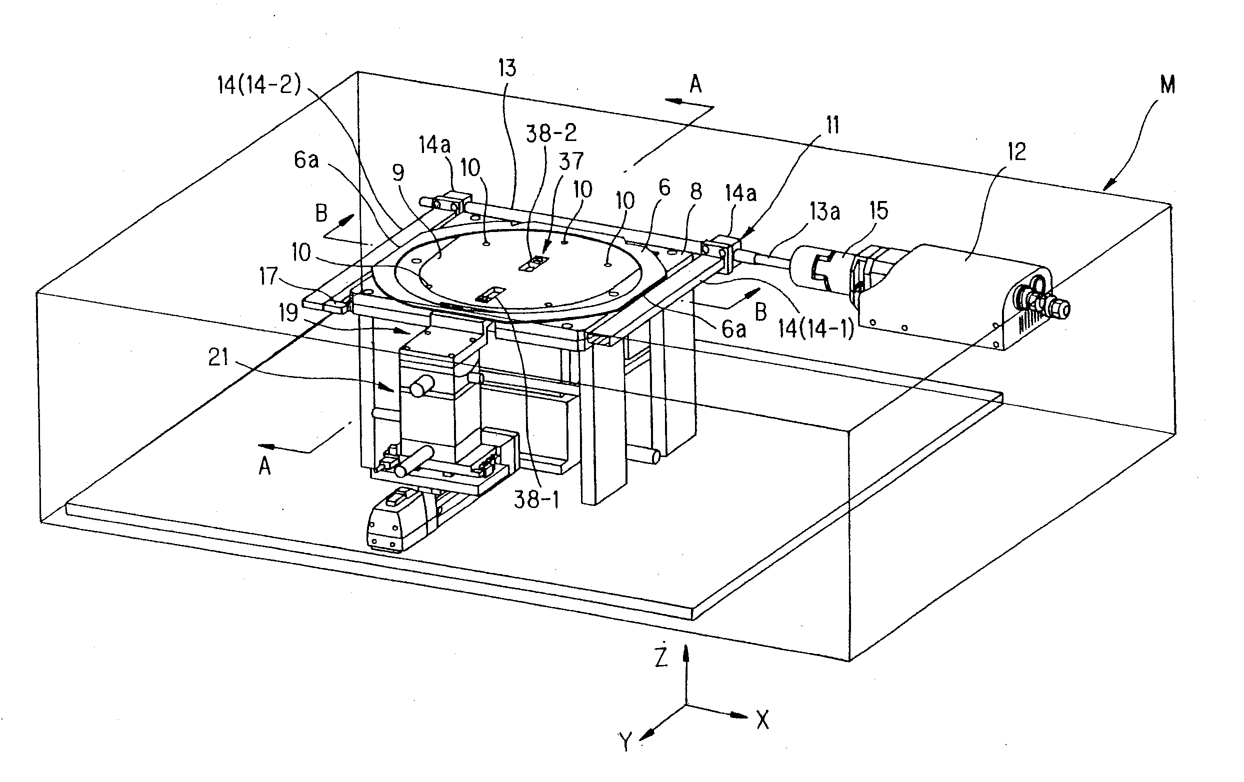
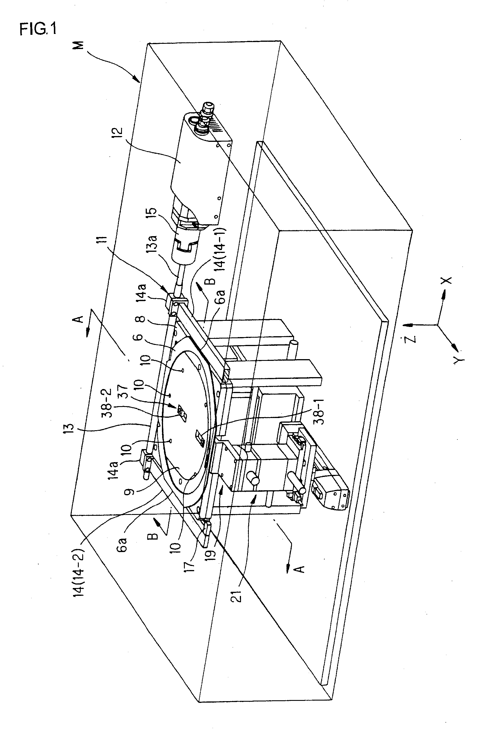
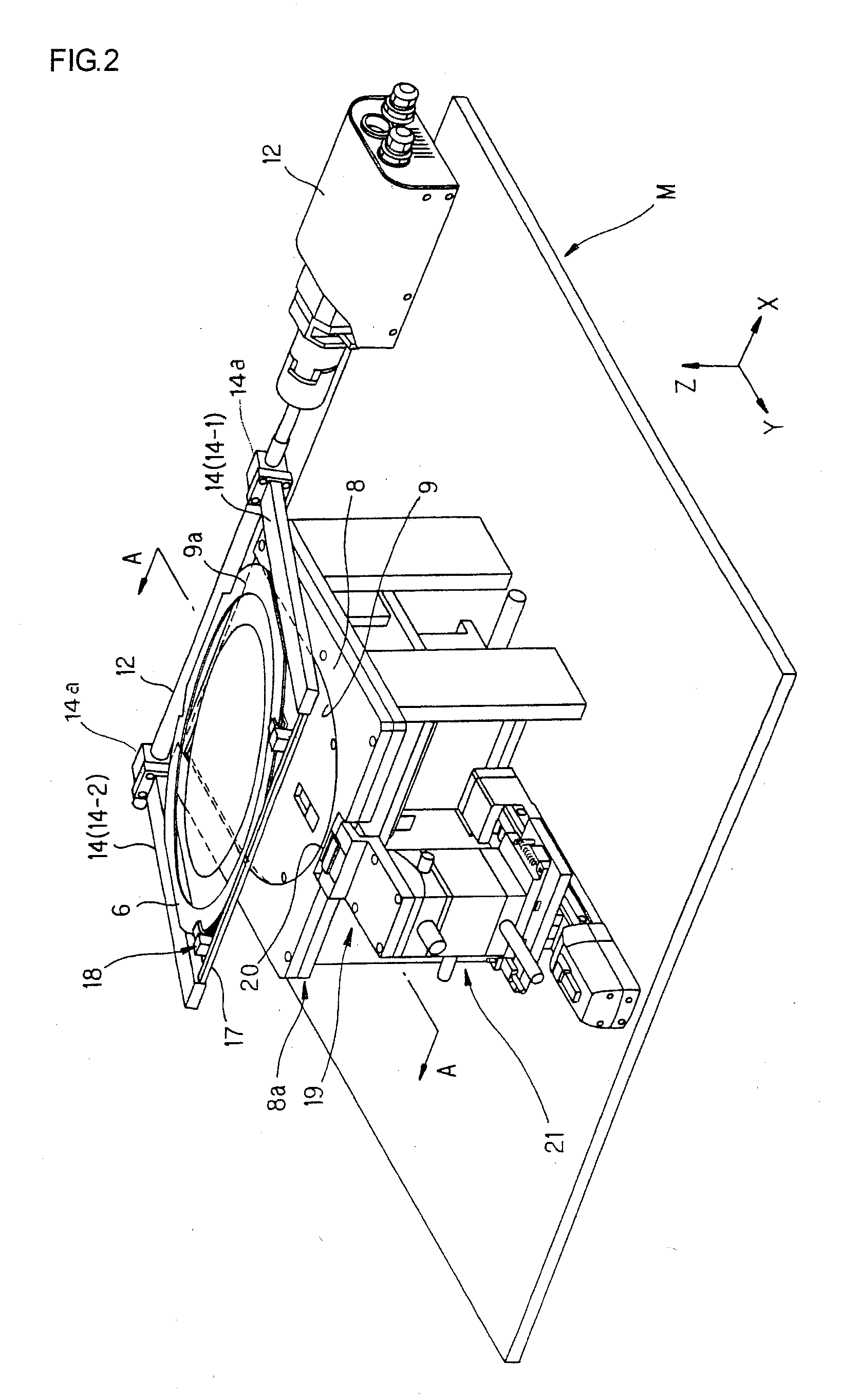
[0021]FIG. 1 is a schematic perspective view of an entire transferring apparatus for a brittle member which is one embodiment of the present invention, FIG. 2 is a schematic perspective view of the transferring apparatus in FIG. 1 during a peeling operation, FIG. 3 is an enlarged perspective view of peeling starting point forming means which constitutes the transferring apparatus in FIG. 1, FIG. 4 is a sectional view of the transferring apparatus on line A-A in FIG. 1, FIG. 5 is a sectional view of the transferring apparatus on line A-A in FIG. 2, FIG. 6 is a sectional view of the transferring apparatus on line B-B in FIG. 1, and FIG. 11 is a sectional view of a peeling target object (stuck structure integrated with a frame through a dicing sheet 7) which is set at a transferring and boding apparatus and the like in FIG. 1.

[0022] First, the peeling target object ...


PUM

PropertyMeasurementUnit
torqueaaaaaaaaaa
brittleaaaaaaaaaa
output torqueaaaaaaaaaa

Abstract

A transferring apparatus for a brittle member capable of peeling a hard member from the brittle member without applying a stress more than required to the brittle member and effectively preventing the brittle member from being damaged by erroneous peeling is provided. When the hard member is peeled off from a stuck structure formed by sticking the brittle member on the top surface of the hard member through a double-sided adhesive sheet to transfer the brittle member onto the adhesive sheet, the adhesive sheet is stuck on the brittle member of the stuck structure to form it integrally with a frame, the hard member side is positioned and fixed onto a table (8), and the frame (6) is raised diagonally upward with respect to the surface of the table with a predetermined torque by a torque control motor (12) with a rotary shaft (13) as a fulcrum. The hard member is peeled off from the brittle member with a force for raising the frame, namely, with the predetermined torque. When the hard member is peeled off, the peeling action is confirmed by peeling confirmation means (37) formed by two reflection type sensors (38-1, 38-2).

Description

TECHNICAL FIELD [0001] The present invention relates to a transferring apparatus for a brittle member, which is used when the brittle member, for example, a semiconductor wafer is processed to be extremely thin in the state in which it is stuck onto a hard member, for example, glass, thereafter, the hard member is peeled off from the brittle member, and the brittle member is transferred to an adhesive sheet such as a dicing sheet. BACKGROUND ART [0002] Conventionally, as a transferring apparatus for a brittle member of this kind, for example, the one with the structure disclosed in, for example, Patent Document 1 is known. The transferring apparatus of this document peels off a hard member 2 from a peeling target object 1 shown in FIG. 11, that is, what is integrated with a frame 6 by sticking an adhesive sheet such as a dicing sheet 7 onto a brittle member 4 of a stuck structure 5 constituted of the hard member 2, and the brittle member 4 which is stuck to its top surface through a...

Claims


Application Information

Patent Timeline
Patent Type & Authority Applications(United States)
IPC IPC(8): B32B38/10
CPCH01L21/67132Y10T156/15Y10T156/12
Inventor AKECHI, TAKESHI
Owner LINTEC CORP
Why Eureka
Try Eureka