
Golf head having a ported construction

a golf head and port technology, applied in the field of golf heads, can solve the problems of reducing the amount of weight available for adjustment, requiring weight for the weighting device, and not allowing quick and easy weight adjustment, etc., to achieve convenient and efficient manufacturing, low cost, and durable and reliable construction

Inactive Publication Date: 2007-12-20
PRINCE SPORTS LLC
View PDF61 Cites 171 Cited by
  • Summary
  • Abstract
  • Description
  • Claims
  • Application Information

AI Technical Summary

Benefits of technology

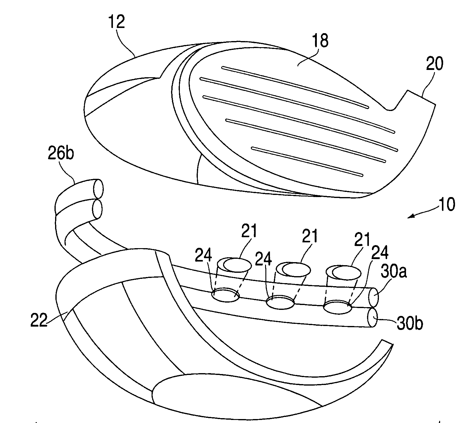
[0020]The peripheral region of the club head body can be comprised of a metal material to increase the perimeter weighting, or weight inserts located inside a light weight material body to achieve a similar effect. Preferably, the light weight body has ports formed along the periphery to accommodate heavy inserts which can be easily inserted and removed to quickly adjust the weight distribution of the club head.
[0034]The present invention provides an improved golf shaft that has a unique look and improved aesthetics.

Problems solved by technology

However, this design does not allow for quick and easy weight adjustment.
This weighting device is removable from the golf head and not integrally molded in, meaning that weight is required for the weighting device which reduces the amount of weight available for adjustment.
The amount of weight adjustment is limited because the club head is made of metal, which is heavy, as well as the threaded sleeves.
It is also limited by the requirement of using threaded means to attach the adjustment weights.
The weight of the removable receptacle limits the amount of adjustment weight.
In addition, this design is limited to the sole of the club head.
This is limited by the weight distribution within each lid portion, and the amount of adjustment weight is limited due to the weight of the lid and engaging means.
It is difficult to precisely locate the weighting material.
It is also possible the weighting material may come loose over time and create a rattle noise.

Method used


Image

  • Golf head having a ported construction
  • Golf head having a ported construction
  • Golf head having a ported construction

Examples


Embodiment Construction

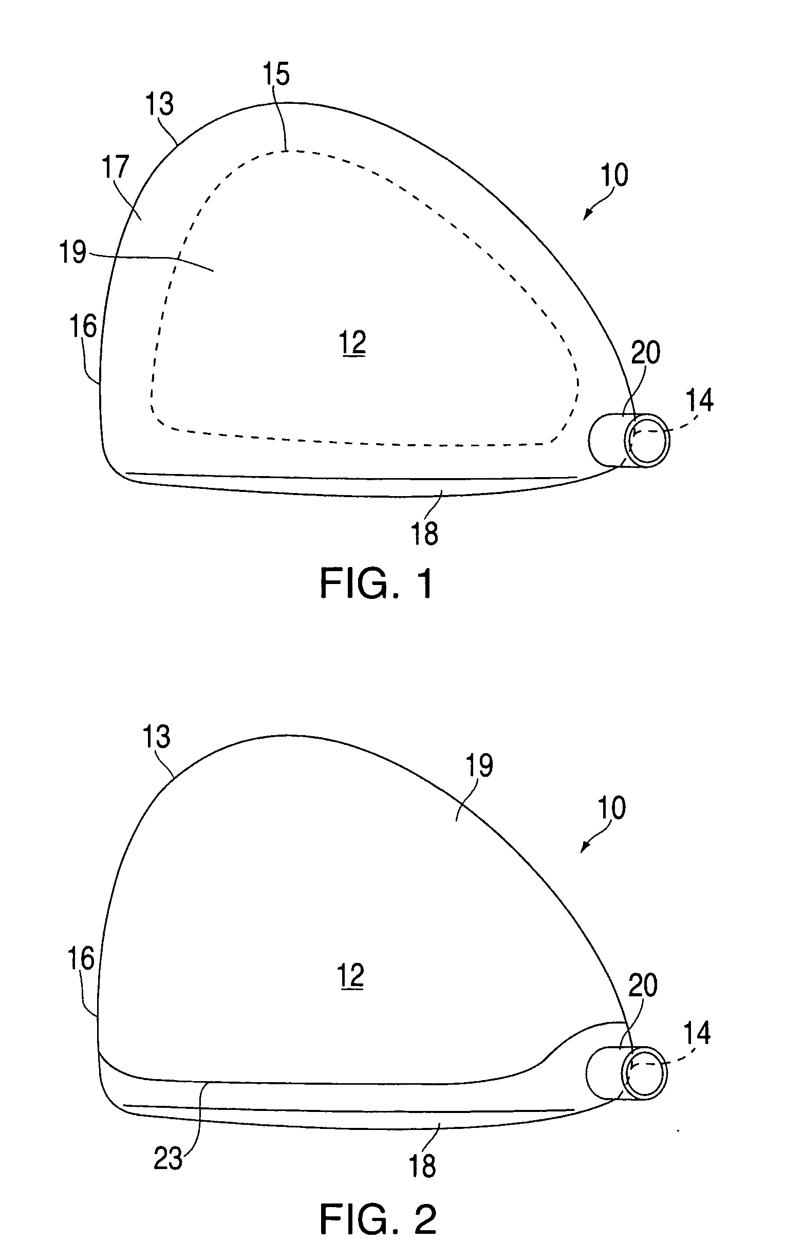
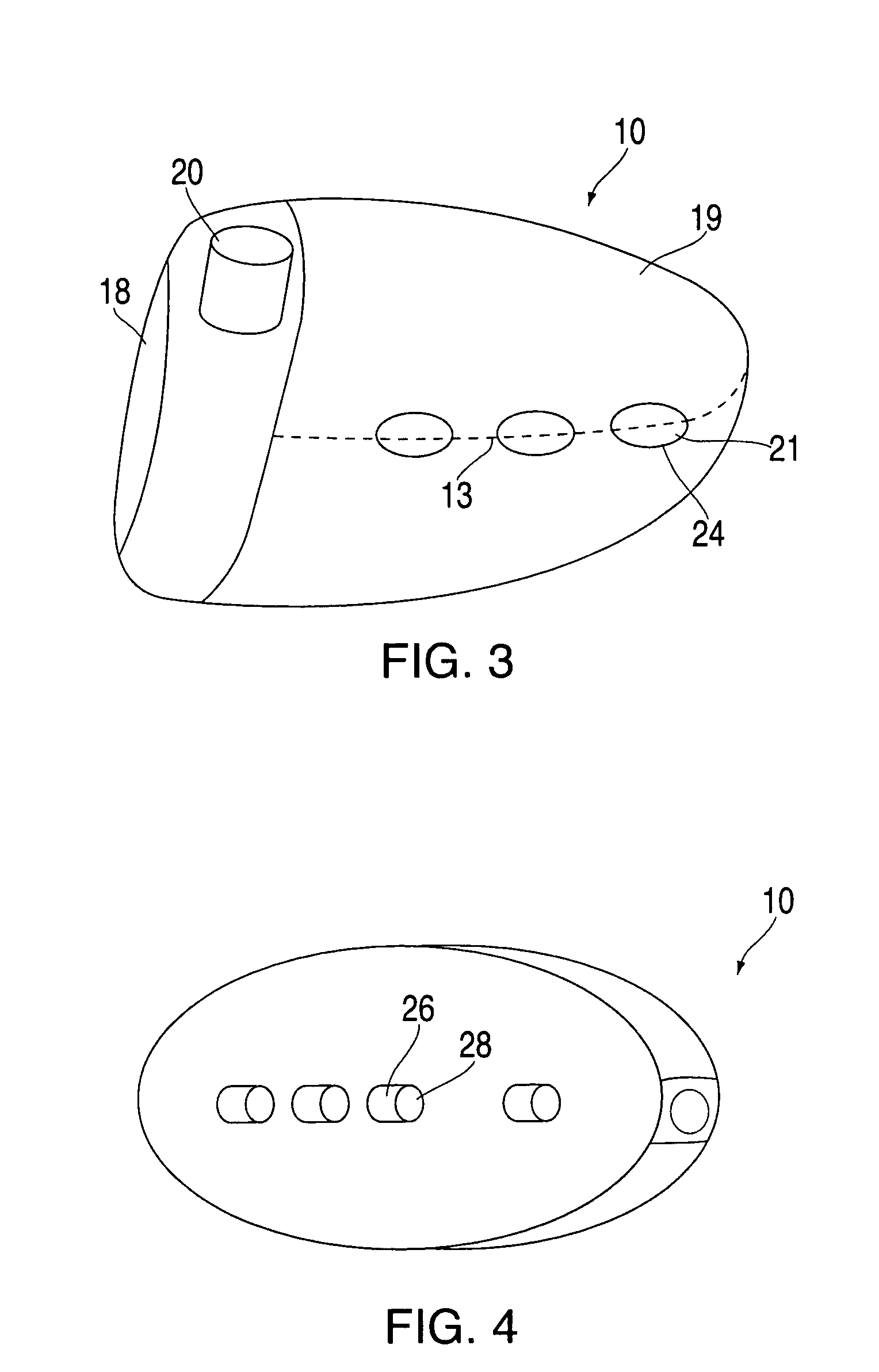
[0052]FIG. 1 shows an example of a driver club head having a hollow body, or shell 10, defining a top surface 12, a heel 14, and a toe 16. The club head further includes a front face 18 and a hosel 20 extending from the top surface 12. The shell 10 defines a hollow interior, and can be comprised of several materials depending on the weight distribution desired. The face 18 may also be selected from various materials and may either be integral with the shell 10 (as in FIG. 1) or a separate piece (as in FIG. 2, described below).

[0053]The shell 10, viewed from above, has an outer periphery 13 which extends from the heel, around the rear of the shell 10, to the toe generally in a horizontal plane. A peripheral region 17, whose approximate boundary is defined by broken line 15, also extends above and below the periphery from the heel, around the rear of the shell 10, to the toe. Thus, a center portion 19 lies inside the boundary 15. A similar center portion is preferably present in the s...


PUM


Abstract

A golf club head has a face, a hosel, and a hollow body. The body includes an outer peripheral region, when viewed from above, and center portions on the upper surface and sole, respectively. The outer peripheral region has a weight-per-unit of surface area which is greater than the weight-per-unit of surface area of the center portions. The weight differential may be accomplished by molding ports into the hollow body around the periphery, which contain weight plugs. Alternately or in addition, a vertically oriented port may extend through the center portions to reduce weight.

Description

BACKGROUND OF THE INVENTION[0001]The present invention relates to a golf head made of multiple materials to achieve variable weight distribution, whereby the central area of the golf head has minimal mass, and the periphery has maximum mass distribution to maximize the rotational inertia of the golf head. In addition, the periphery is comprised of molded ports to facilitate weight adjustment means.[0002]The performance of a golf head is determined by the physical characteristics of the head such as weight, weight distribution, and rotational moment of inertia. There are other geometric factors which play a role such as face size, face angle, offset, lie angle, etc., but these are not the purpose of the present invention.[0003]The present invention can be applied to a “wood” type head such as a driver or fairway wood, and also a putter. The objective is to take advantage of light weight materials such as fiber reinforced composites, which can provide a reduced weight in the central r...

Claims


Application Information

Patent Timeline
IPC IPC(8): A63B53/00
CPCA63B53/0466A63B53/0487A63B59/0092A63B2053/0416A63B2053/0437A63B2209/023A63B49/06A63B2053/0433A63B2053/0491A63B60/52A63B60/54A63B53/0437A63B53/0416A63B53/0433A63B60/02
Inventor DAVIS, STEPHEN J.
Owner PRINCE SPORTS LLC
Learn More