
Optical disk drive

Inactive Publication Date: 2007-12-20
KONICA MINOLTA INC
View PDF14 Cites 0 Cited by
  • Summary
  • Abstract
  • Description
  • Claims
  • Application Information

AI Technical Summary

Benefits of technology

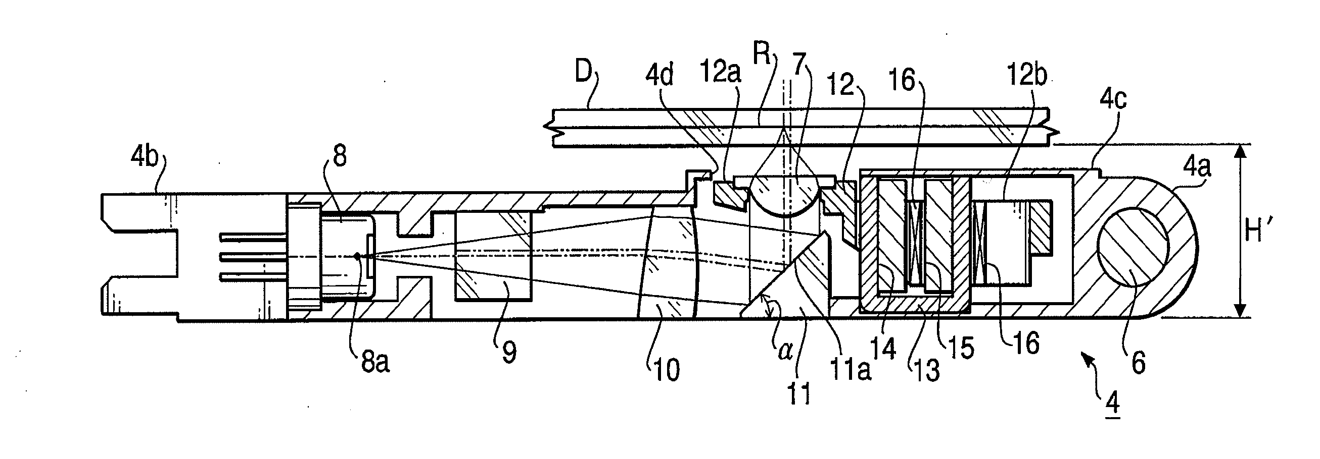
[0007] In view of the foregoing drawbacks, the present invention is advantageous in that an optical disk drive having a carriage with a smaller configuration in its height is provided. In the carriage, an area to be occupied by a vertical reflection mirror taken from a direction perpendicular to an optical disk can be configured to be smaller by inclining a path of laser beam to enter the vertical reflection mirror at a larger angle. Further, an objective lens of the optical disk drive is configured to be an infinite system so that optical property of the laser beam that may otherwise be deteriorated can be maintained while a number of additional components to be used in the optical disk drive is minimized.

Problems solved by technology

In the configuration disclosed in the above-referenced publication, however, an inclination angle of the semiconductor laser 110 is limited, thus an inclination of the beam emitting from the semiconductor laser to the vertical reflection mirror 102 is also limited.

Method used


Image

  • Optical disk drive
  • Optical disk drive
  • Optical disk drive

Examples


Embodiment Construction

[0019] Hereinafter, referring to the accompanying drawings, according to illustrative embodiments of the invention will be described.

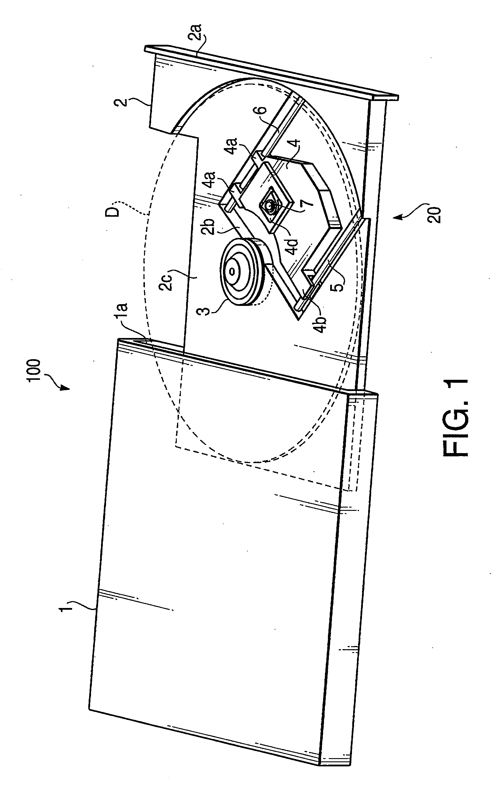
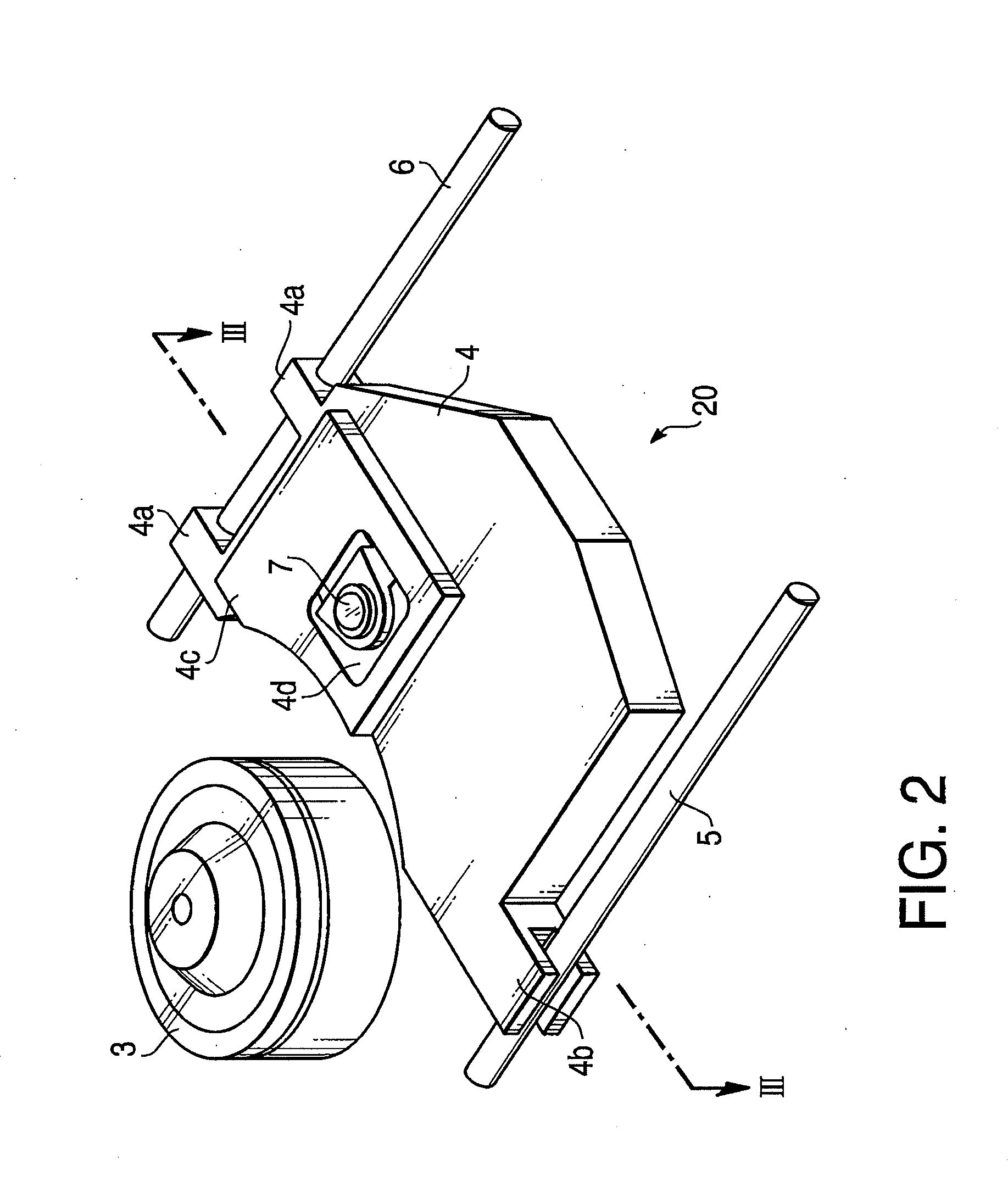
[0020]FIG. 1 is a perspective view showing a structure of an optical disk drive 100 having an optical pickup unit 20 according to the embodiment of the present invention. As shown in FIG. 1, the optical disk drive 100 according to the present invention includes a casing 1 having a thin boxed-shape to be incorporated in a chassis of a personal computer (not shown), and a tray 2 capable of being inserted in and ejected from the casing 1 through a slit 1a provided on one side of the casing 1. An optical disk D can be placed on and removed from the tray 2 as the tray 2 is ejected from the casing 1. As the tray 2 is inserted in the casing 1, the optical disk D is held in the casing 1, and the slit 1a of the casing 1 is closed by a cover surface 2a of the tray 2.

[0021] Additionally, in the present embodiment, a spindle 3 and a carriage 4, which serve mainl...


PUM


Abstract

An optical disk drive for recording information on a recording surface of an optical disk and reading information recorded in the optical disk is provided. The optical disk drive includes a spindle to rotate the optical disk and a carriage movable in parallel with a tracking direction of the optical disk. The carriage includes a laser light source to emit laser light, a collimator lens to convert divergent light into parallel light and is arranged with an optical center thereof being in a farther and offset position with respect to an optical axis of the laser light, a reflecting mirror to receive and deflect the laser light transmitted through the collimator lens in a direction perpendicular to the recording surface of the optical disk, and an objective lens to converge the laser light deflected by the reflecting mirror on a position corresponding to the recording surface of the optical disk.

Description

BACKGROUND OF THE INVENTION [0001] The present invention relates to an optical disk drive, which is capable of converging laser beam on a recording surface of an optical disk so that information can be written on and read from the recording surface. [0002] Generally, an optical pickup used in an optical disk drive, which records optical information in an optical disk as a recording medium such as a CD (compact disk) and a DVD (digital versatile disk) and reads such optical information from the optical disk, is configured to converge laser beam emitted from a semiconductor laser on a recording surface of the optical disk. Specifically, the laser beam emitted from the semiconductor laser is deflected perpendicularly by a vertical reflection mirror toward the optical disk. The vertical reflection mirror is mounted on a carriage which is movable in a direction to track the optical disk. The deflected laser beam is then converged on the recording surface of the optical disk by an objecti...

Claims


Application Information

Patent Timeline
IPC IPC(8): G11B7/00
CPCG11B7/1205G11B7/08582G11B7/123
Inventor TAKISHIMA, SUGURUNISHIKAWA, HIROSHIKANAZAWA, HIROSHIHONMA, RYOSEI
Owner KONICA MINOLTA INC
Learn More