
Fluid control system, device and method

a technology of fluid control and control system, applied in the direction of valve operating means/release devices, electric generator control, machines/engines, etc., can solve the problems of large battery to maintain, device bulky, and inability to retrofit to existing plumbing and faucets, and achieve the effect of increasing the moisture level in the soil

Inactive Publication Date: 2007-12-13
KHORSHID OBALIT
View PDF23 Cites 24 Cited by
  • Summary
  • Abstract
  • Description
  • Claims
  • Application Information

AI Technical Summary

Benefits of technology

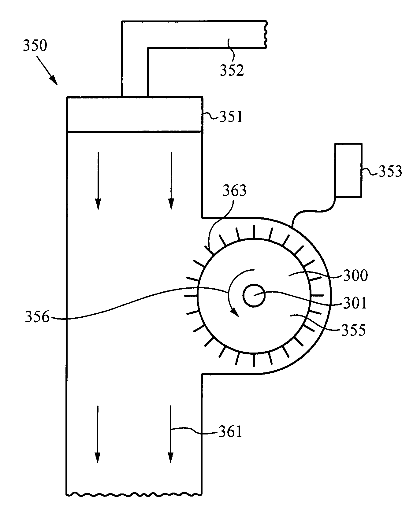
"The present invention is a fluid control system that includes a sensor unit for measuring various conditions and a valve unit that automatically opens and closes in response to the sensor unit. The sensor unit can measure light, temperature, chemical compositions, water levels, or the presence of an object or body. The fluid control system also includes a power generator unit that uses a magnetic micro-generator to generate power from the flow of fluid through the system. The power generated is stored in a battery and used to power the valve unit and the sensor unit. The system can be used in sprinkler systems for controlling the flow of water based on the measured condition. The invention provides a more efficient and automated control system for fluid flow."

Problems solved by technology

These prior art fluid control devices can in general only be installed with new construction and are difficult to retrofit to existing plumbing and faucets.
This device, however, is bulky and requires a large battery to maintain and operate it.
Further, this device has limited applications and can only be used for controlling a flow of water through a faucet.

Method used


Image

  • Fluid control system, device and method
  • Fluid control system, device and method
  • Fluid control system, device and method

Examples


Embodiment Construction

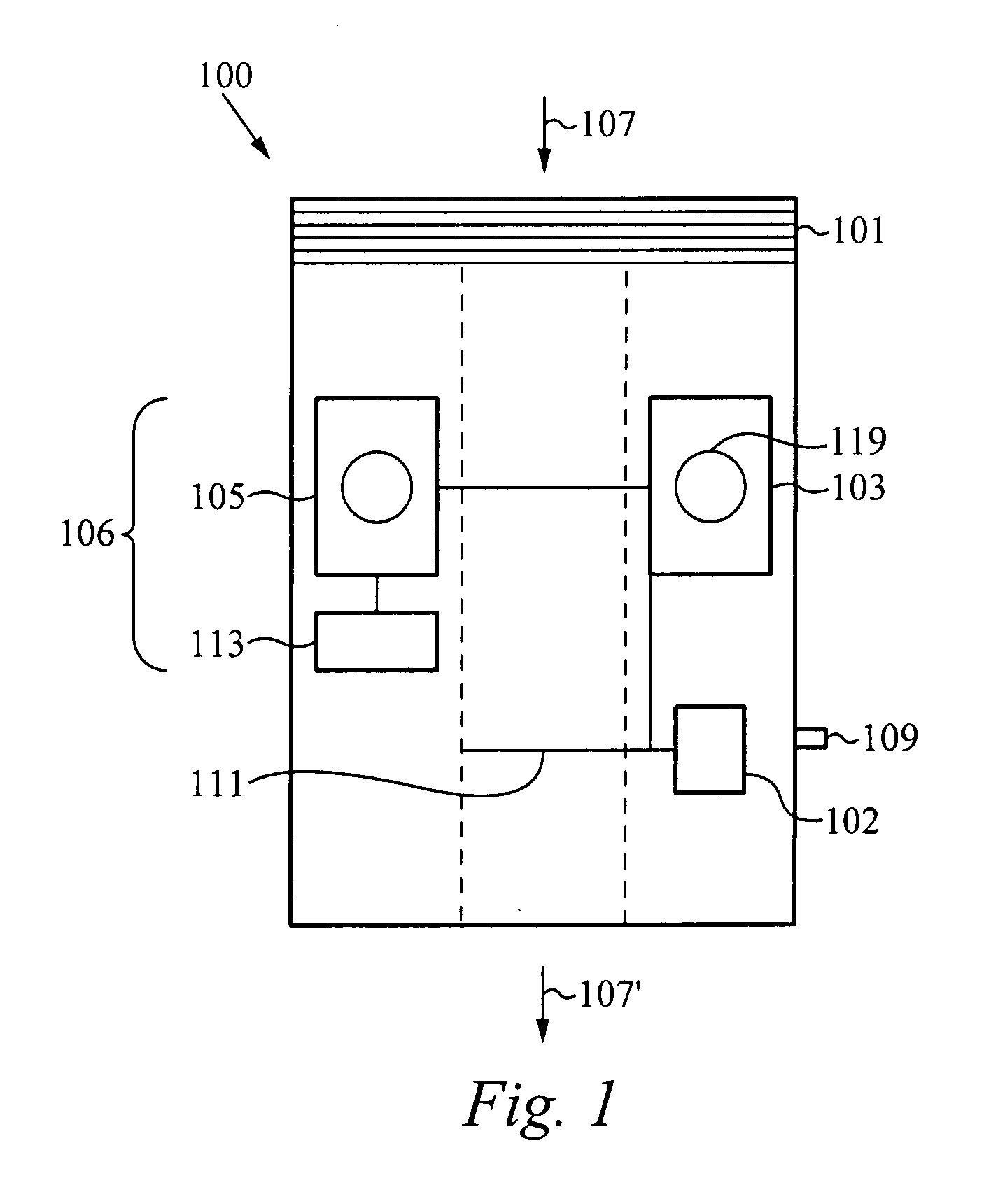
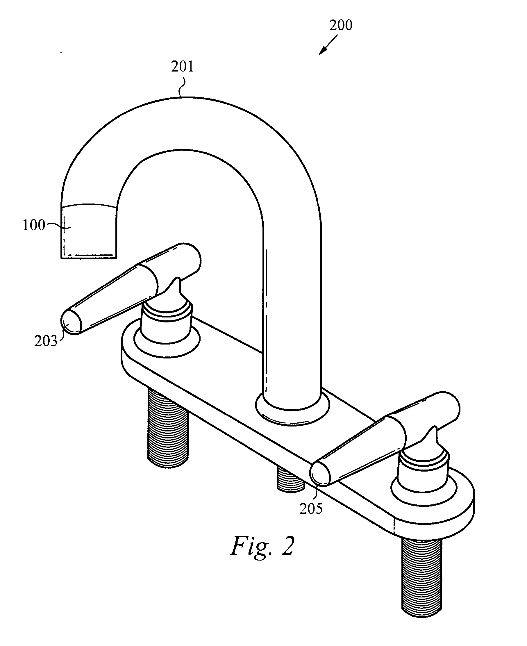
[0021]FIG. 1 illustrates a schematic representation of a fluid control unit 100, in accordance with the embodiments of the invention. The fluid control unit 100 includes means 101 to couple the fluid control unit 100 to a fluid source (not shown). The means 101 to couple the fluid control unit 100 to a fluid source can include one or more threaded features, pipe fittings or any other suitable features or mechanisms that allow the fluid control unit 100 to couple to the fluid source and be positioned in a path of a flow of fluid, as indicated by the arrows 107 and 107′.

[0022]The fluid control unit 100 in includes a sensor unit 103 for sensing a condition. The sensor unit 103 includes a sensor 119 that is photo sensor, a thermal sensor, an electrode, a moisture sensor or an occupancy sensor for detecting or measuring light, temperature, chemical compositions, water or moisture levels or the presence of an object or body, respectively. The fluid control unit 100 further includes a valv...


PUM


Abstract

A fluid control system, device and method are disclosed. The fluid control device is preferably configured to connect to an outlet of a fluid source. The fluid control device includes a valve, a sensor, a battery and a micro-generator. The sensor is used to measure or detect a condition and provide output signals that open and close the valve in response to a measured or detected condition. The micro-generator is positioned in a flow path of fluid and generates power from a flow of the fluid. The power generated from the micro-generator is stored in the battery and used to power later operations of the device. The device can be used for automating faucets, sprinklers and fire extinguishing equipment.

Description

RELATED APPLICATIONS[0001]This Application claims priority under 35 U.S.C. § 119(e) from the Co-pending U.S. Provisional Patent Application Ser. No. 60 / 789,771, filed on Apr. 6, 2006, and titled “MICRO-GENERATOR CONTROL SYSTEMS,” the contents of which are hereby incorporated by reference.FIELD OF THE INVENTION[0002]This invention relates generally to control systems, devices and methods. More specifically, this invention relates to fluid control systems, devices and methods.BACKGROUND OF THE INVENTION[0003]A fluid control device, such as a fluid control device that automatically opens and closes a faucet in response to an infrared occupancy sensor, typically requires wiring and circuitry to be installed. These prior art fluid control devices can in general only be installed with new construction and are difficult to retrofit to existing plumbing and faucets.[0004]The U.S. Pat. No. 6,420,737 describes a fluid control device that can be adapted to an existing faucet. This device, howe...

Claims


Application Information

Patent Timeline
Patent Type & Authority Applications(United States)
IPC IPC(8): F16K31/02
CPCH02K7/1823E03C1/055Y10T137/7761Y10T137/0324
Inventor KHORSHID, OBALIT
Owner KHORSHID OBALIT
Learn More