
Radio Frequency Identification (Rfid) Label Applicator

a technology of radio frequency identification and label applicator, which is applied in the direction of instruments, transportation and packaging, packaging, etc., can solve the problems of inability to apply labels to items or products, inconsistent number of labels between the point of detection and the point of rejection, and inability to detect defective labels

Inactive Publication Date: 2007-12-13
SENSORMATIC ELECTRONICS CORP
View PDF4 Cites 11 Cited by
  • Summary
  • Abstract
  • Description
  • Claims
  • Application Information

AI Technical Summary

Benefits of technology

This solution enables precise detection and rejection of defective RFID labels without interrupting the application process, maintaining high productivity by ensuring only valid labels are applied to products, thereby reducing the risk of applying defective labels and minimizing production line slowdowns.

Problems solved by technology

Existing RFID applicators, however, have encountered problems in handling defective labels.
One problem occurs when tracking a defective label from the point at which it is detected to the point at which it can be rejected.
Because of potential differences in the RFID label footprints and web paths through the applicator, the number of labels between the point of detection and the point of rejection may be inconsistent.
As a result of this inconsistency, an applicator may reject a good label and may apply a defective label to the product.
Another problem is that the rejection of defective RFID labels may interrupt the label application process and may result in labels not being applied to items or products.
Each defective label that is encountered may cut the product application rate by up to an additional 50%.

Method used


Image

  • Radio Frequency Identification (Rfid) Label Applicator
  • Radio Frequency Identification (Rfid) Label Applicator
  • Radio Frequency Identification (Rfid) Label Applicator

Examples


Embodiment Construction

[0020] Numerous specific details may be set forth herein to provide a thorough understanding of the embodiments of the disclosure. It will be understood by those skilled in the art, however, that various embodiments of the disclosure may be practiced without these specific details. In other instances, well-known methods, procedures, components and circuits have not been described in detail so as not to obscure the various embodiments of the disclosure. It can be appreciated that the specific structural and functional details disclosed herein are representative and do not necessarily limit the scope of the disclosure.

[0021] It is worthy to note that any reference in the specification to “one embodiment” or “an embodiment” according to the present disclosure means that a particular feature, structure, or characteristic described in connection with the embodiment is included in at least one embodiment. The appearances of the phrase “in one embodiment” in various places in the specific...


PUM

PropertyMeasurementUnit
angleaaaaaaaaaa
peel adhesion strengthaaaaaaaaaa
operating frequencyaaaaaaaaaa

Abstract

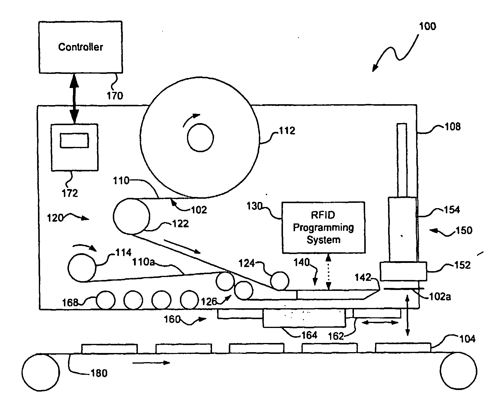
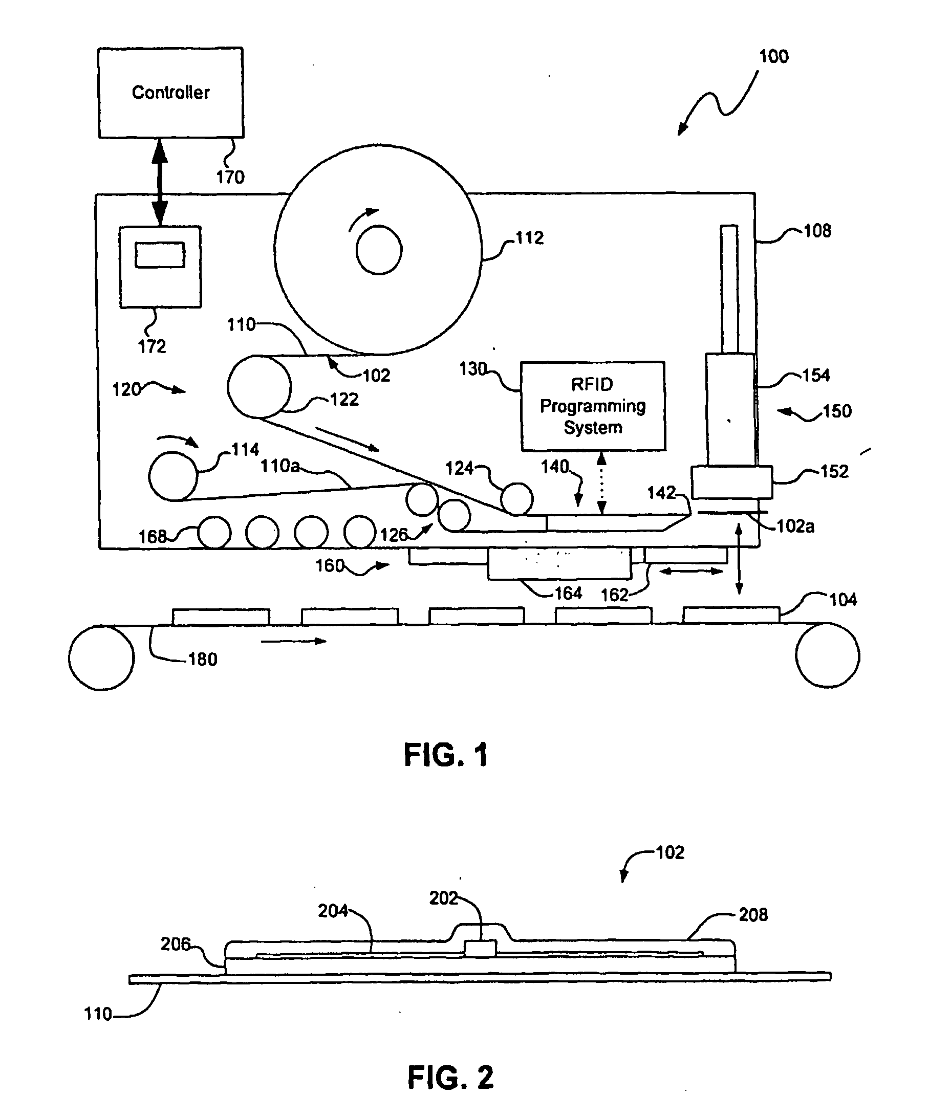
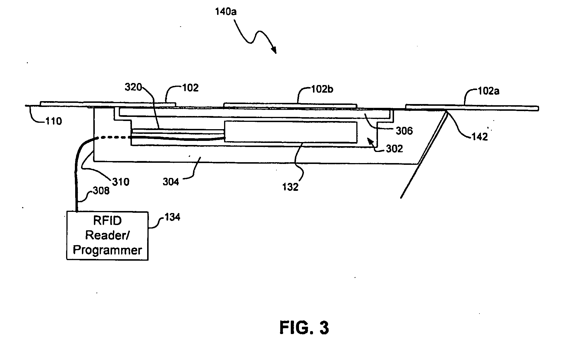
The invention relates to an RFID label applicator (100) may include a peeler member (140) having a peel end (142), the peeler member being configured to cause an RFID label (102) to peel away from a web (110) when the web passes around the peel end; and a label tamp assembly (150) having a receiving surface (612) configured to receive the RFID label and to move it into contact with an item (104) on which the RFID label is to be applied, the label tamp assembly having at least one forward opening in a portion of the receiving surface away from the peeler member and a plurality of rearward openings in a portion of the receiving surface proximate the peeler member, wherein at least one of the forward or rearward openings is configured to draw in air such that a leading portion of the RFID label is substantially secured.

Description

TECHNICAL FIELD [0001] The present application relates to radio frequency identification (RFID) label applicators, and more particularly, to a RFID label applicator capable of programming RFID labels, detecting defective RFID labels and rejecting the defective RFID labels. BACKGROUND INFORMATION [0002] Radio frequency identification (RFID) systems are generally known and may be used for a number of applications such as managing inventory, electronic access control, security systems, automatic identification of cars on toll roads, and electronic article surveillance (EAS). RFID devices may be used to track or monitor the location and / or status of articles or items to which the RFID devices are applied. A RFID system typically comprises a RFID reader and a RFID device such as a tag or label. The RFID reader may transmit a radio-frequency carrier signal to the RFID device. The RFID device may respond to the carrier signal with a data signal encoded with information stored on the RFID d...

Claims


Application Information

Patent Timeline
Patent Type & Authority Applications(United States)
IPC IPC(8): B65C9/18
CPCB65C9/1884B65C2009/0003Y10T156/1707B65C2009/405G06K2017/0041B65C2009/0093G08B13/2417
Inventor FORD, JOHN C.MARCUS, CHRISTOPHER
Owner SENSORMATIC ELECTRONICS CORP
Learn More