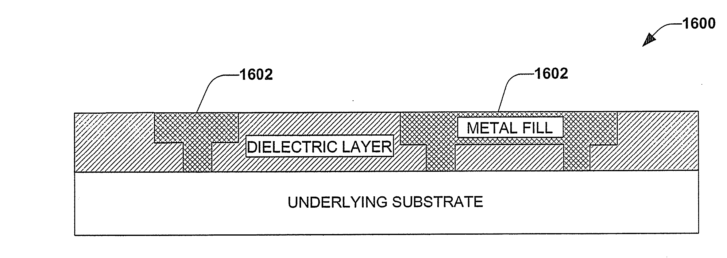
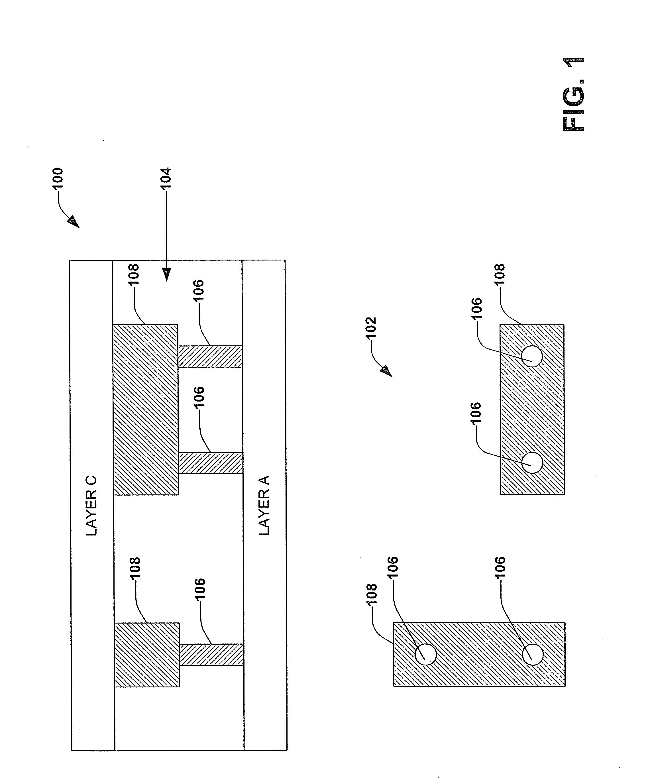
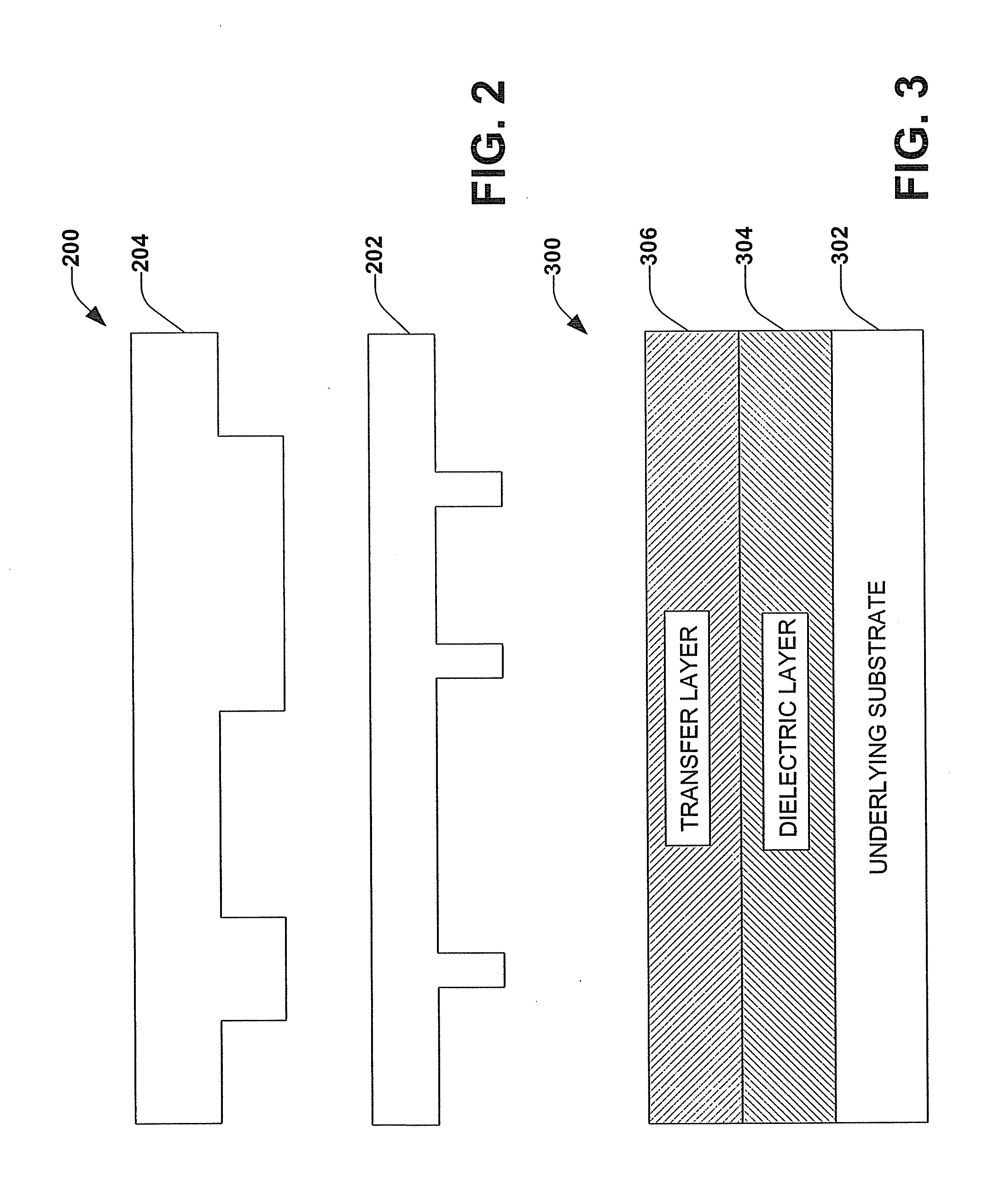
System and method for imprint lithography to facilitate dual damascene integration with two imprint acts
a technology of imprint lithography and system, applied in the field of system and method of imprint lithography, can solve the problems of difficult to achieve small feature size and significant capital investment of optical equipment for traditional photolithographic processes
- Summary
- Abstract
- Description
- Claims
- Application Information
AI Technical Summary
Benefits of technology
Problems solved by technology
Method used
Image

Examples
Embodiment Construction
[0042] The present invention will now be described with reference to the drawings. The following detailed description is of the best mode presently contemplated by the inventors for practicing the invention. It should be understood that the description of these aspects are merely illustrative and that they should not be taken in a limiting sense.
[0043] As used in this application, the terms “mold”, “imprint mold”, and “imprint lithography mold” are used interchangeably to refer to an article comprising a three dimensional pattern used to imprint a pattern in deformable material utilized in the production of an integrated circuit. The terms “imprint lithography” and “nanoimprint lithography” are used interchangeably to describe a method of producing integrated circuits involving imprinting a pattern onto a resist and subsequent exposure by a source, typically ultraviolet light, to which the resist is reactive.
[0044] Furthermore, the term “component” as used in this application is i...
PUM
| Property | Measurement | Unit |
|---|---|---|
| translucent | aaaaa | aaaaa |
| dielectric | aaaaa | aaaaa |
| dielectric etch | aaaaa | aaaaa |
Abstract
Description
Claims
Application Information
 - R&D
- Intellectual Property
- Life Sciences
- Materials
- Tech Scout
- Unparalleled Data Quality
- Higher Quality Content
- 60% Fewer Hallucinations
Browse by: Latest US Patents, China's latest patents, Technical Efficacy Thesaurus, Application Domain, Technology Topic, Popular Technical Reports.
© 2025 PatSnap. All rights reserved.Legal|Privacy policy|Modern Slavery Act Transparency Statement|Sitemap|About US| Contact US: help@patsnap.com