
Thoracentesis catheter system with self-sealing valve

a thoracentesis catheter and self-sealing technology, applied in the field of medical devices, can solve the problems of existing thoracentesis devices exhibiting drawbacks, risk of lung collapse, and risk of lung collaps

Inactive Publication Date: 2007-12-06
MAYSE MARTIN L
View PDF1 Cites 36 Cited by
  • Summary
  • Abstract
  • Description
  • Claims
  • Application Information

AI Technical Summary

Benefits of technology

[0007]The present invention provides thoracentesis systems composed of an insertion needle, a thoracentesis catheter with self-sealing valve, and a valve opening device utilized in invasive medical procedures. The insertion needle is utilized to insert the thoracentesis catheter with self-sealing valve into the pleural cavity. The needle is withdrawn and the thoracentesis catheter remains in the pleural cavity creating a potential drainage path out of the pleural cavity. The self-sealing valve automatically closes upon removal of the needle from the thoracentesis catheter. Automatic closing of the self-sealing valve prevents fluid from draining out of the pleural cavity through the thoracentesis catheter and prevents air from entering the pleural cavity through the thoracentesis catheter. A flo

Problems solved by technology

Existing thoracentesis devices have exhibited drawbacks.
If negative pressure is not present or not maintained on the flow path, air can enter the pleural cavity and a risk of lung collapse exists.
However, if the valve is not manually closed, an open flow path through the open valve allows entry of air into to the pleural cavity and a risk of lung collapse exists.
These systems are cumbersome to use and when the manually actuated valve is open and negative pressure is not present on the flow path, air can enter into the pleural cavity and a risk of lung collapse exists.

Method used


Image

  • Thoracentesis catheter system with self-sealing valve
  • Thoracentesis catheter system with self-sealing valve
  • Thoracentesis catheter system with self-sealing valve

Examples


Embodiment Construction

[0014]Although the present invention can be made in many different forms, a preferred embodiment is described in this disclosure and shown in the attached drawings. This disclosure exemplifies the principles of the present invention and does not limit the broad aspects of the invention only to the illustrated embodiments.

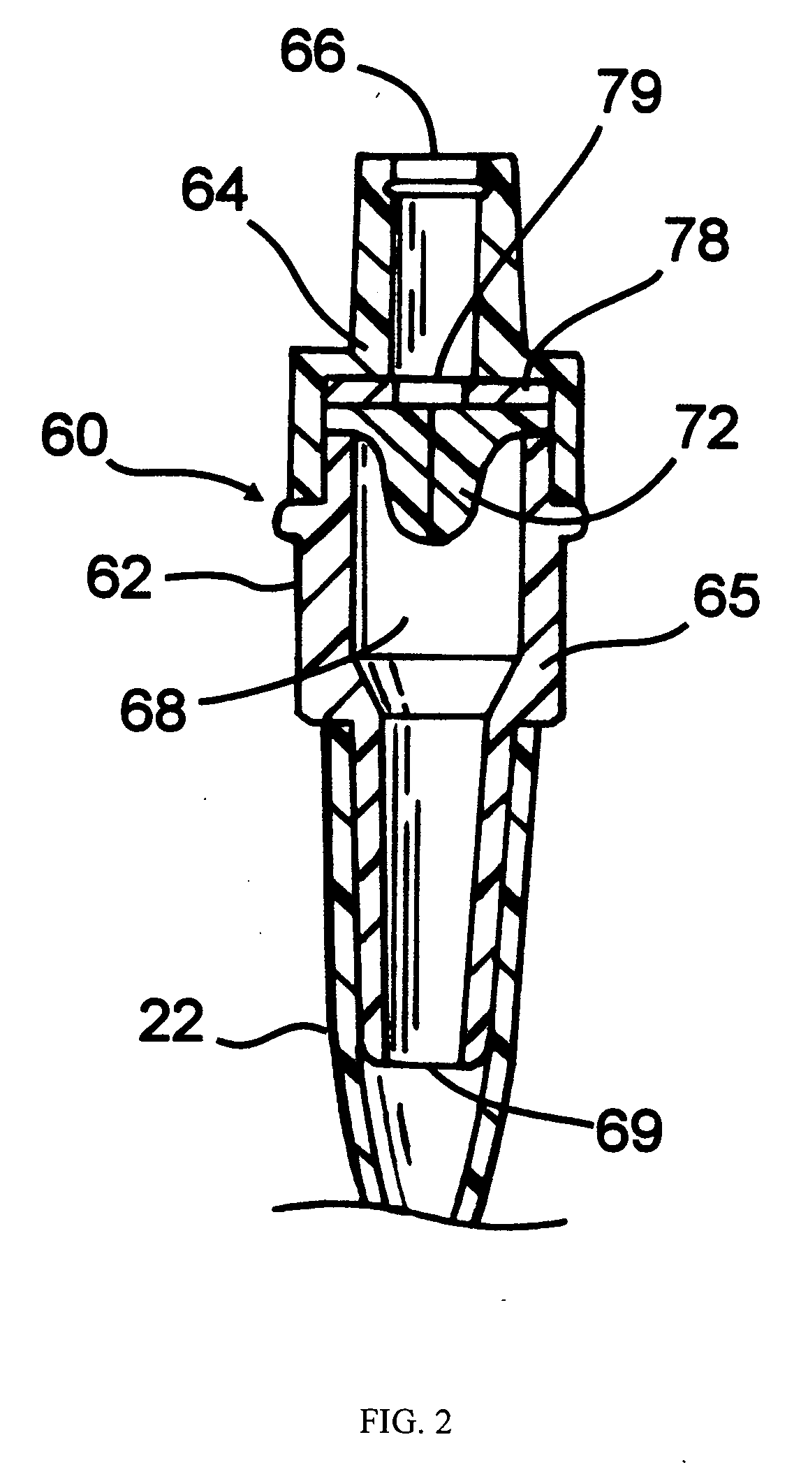
[0015]FIG. 1 shows an elevational view of a thoracentesis catheter with self sealing valve 10 made in accordance with the principles of the present invention. The thoracentesis catheter with self sealing valve 10 includes an elongated catheter 20 with a catheter hub 22 and a self-sealing valve 60. The catheter 20 is fixedly attached to the catheter hub 22 and the catheter hub 22 is fixedly attached to the self-sealing valve 60. An elongated insertion needle 14 extends through the catheter 20, through the catheter hub 22 and through the self-sealing valve 60. A syringe 12 is removably connected to the insertion needle 14 by an interference fit or luer fitting 16. The...


PUM


Abstract

The present invention provides thoracentesis systems composed of an insertion needle, a thoracentesis catheter with self-sealing valve, and a valve opening device which are utilized in the removal of fluid or gases from a pleural cavity. The insertion needle is utilized to insert the thoracentesis catheter into the pleural cavity. The thoracentesis catheter provides automatic closure of the flow path from the pleural cavity by automatic closure of the self-sealing valve upon removal of the insertion needle from the thoracentesis catheter. The self-sealing valve prevents drainage of fluid from the pleural cavity and introduction of air into the pleural cavity when the needle is withdrawn from the thoracentesis catheter and a valve opening device is not in place. A drainage flow path from the pleural cavity is established by insertion of a valve opening device into the self-sealing valve of the thoracentesis catheter, thus opening the self-sealing valve. With the self-sealing valve opened by a valve opening device, fluid or gases can be removed from the pleural cavity.

Description

BACKGROUND OF THE INVENTION[0001]This invention generally relates to medical devices utilized in invasive medical procedures. More specifically, this invention relates to thoracentesis systems composed of an insertion needle, a thoracentesis catheter with self-sealing valve, and a valve opening device which are utilized in combination for the removal of fluid or gases from a pleural cavity.[0002]A thoracentesis procedure is a medical procedure for removing or draining fluid or gases from a pleural cavity of a patient. The thoracentesis procedure includes insertion of a thoracentesis device into a pleural cavity and creating a flow path from the pleural cavity in order to remove fluids or gases from the pleural cavity.[0003]Typically, a needle is utilized to insert a catheter into the pleural cavity. The needle is withdrawn and the catheter remains in the pleural cavity creating a flow path out of the pleural cavity. Negative pressure is applied to the flow path to remove fluid from ...

Claims


Application Information

Patent Timeline
IPC IPC(8): A61M5/178
CPCA61M25/0606A61M2039/0633A61M2039/062A61M39/0606
Inventor MAYSE, MARTIN L.
Owner MAYSE MARTIN L
Learn More