
Action languages for unified modeling language model

a technology of unified modeling and language model, applied in the direction of source code generation, instruments, requirement analysis, etc., can solve the problems of not being skilled in programming languages and coding, not defining formal and precise enough semantics in the language model, and difficult to use statecharts to capture all behavioral aspects of the system

Active Publication Date: 2007-11-29
THE MATHWORKS INC
View PDF20 Cites 122 Cited by
  • Summary
  • Abstract
  • Description
  • Claims
  • Application Information

AI Technical Summary

Benefits of technology

[0013] The graphical model may include extensive textual aspects that can be declarative as well as imperative in nature. In addition, the graphical model may include dynamically typed and statically typed aspects. The graphical action language of the present invention enables a user to graphically program the methods or behaviors of a UML model or components in the UML model so that the UML model can be easily converted to executable code.

Problems solved by technology

UML does not define a formal and precise-enough semantic to allow a user to automatically build an executable model.
Though the behavior of the system can be modeled by statecharts, which is an imperative and untimed language based on state transition diagrams, it is difficult to use statecharts to capture all behavioral aspects of a system.
Unfortunately, UML model designers are generally software architects who construct the UML model at an abstract level and are not always skilled in programming languages and coding.
These languages are well-suited for specifying the finer details of sequences of computations, but are poorly suited for implementing extensive applications such as business software applications.
Developing applications with imperative programming languages is tedious and error prone.
These limitations of imperative programming languages are reflected in the development time and expense and defects found in present day software.
The problems are compounded for real-time computation-intensive systems.
The need for using text-based imperative programming languages to write methods for UML models makes it difficult to employ UML for the design of mission critical functions in real-world applications, such as medical, aerospace or automobile applications.

Method used


Image

  • Action languages for unified modeling language model
  • Action languages for unified modeling language model
  • Action languages for unified modeling language model

Examples


Embodiment Construction

[0039] Certain embodiments of the present invention are described below. It is, however, expressly noted that the present invention is not limited to these embodiments, but rather the intention is that additions and modifications to what is expressly described herein also are included within the scope of the invention. Moreover, it is to be understood that the features of the various embodiments described herein are not mutually exclusive and can exist in various combinations and permutations, even if such combinations or permutations are not made express herein, without departing from the spirit and scope of the invention.

[0040] One embodiment of the present invention provides an action language for modeling the temporal behavior of a unified modeling language (UML) model. Declarative and dynamically typed action languages may be provided for modeling the behavior of physical, control, real-time and computation-intensive systems of a UML model. The behavioral model corresponds to ...


PUM


Abstract

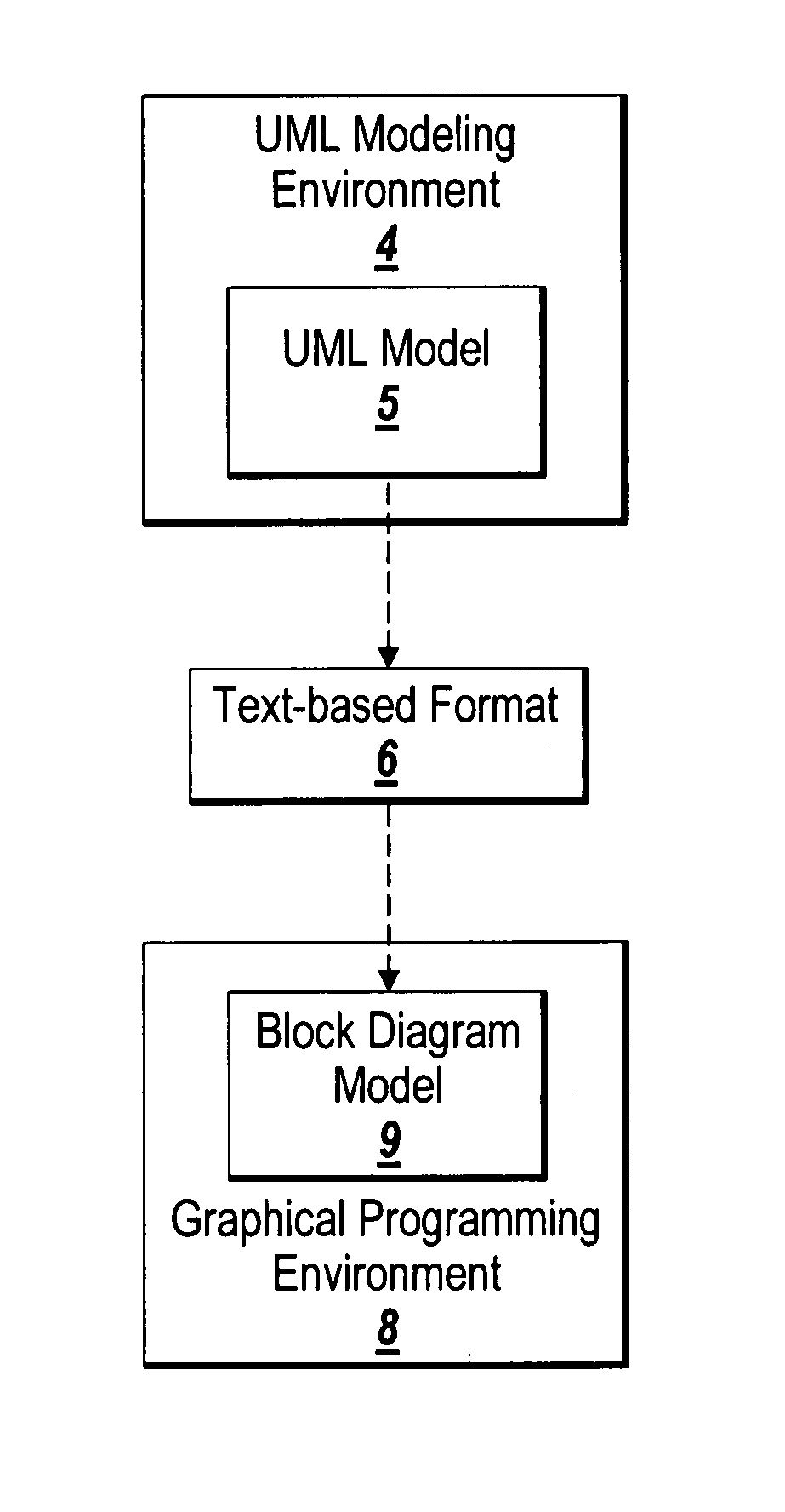
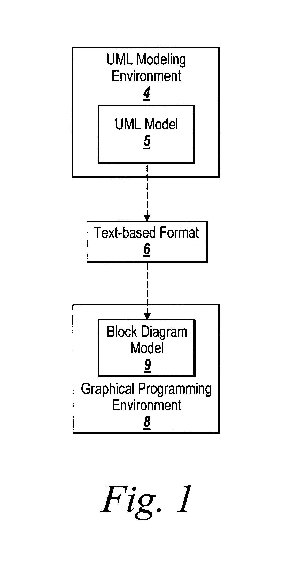
Methods, mediums and systems are provided to enable a user to program the behaviors of a Unified Modeling Language (UML) model in a graphical programming or modeling environment, such as block diagram programming environment. The UML model is exported into a text-based format, which is subsequently imported into the graphical programming or modeling environment. The graphical programming or modeling environment represents the UML model using functional blocks so that the user can program the behaviors of the UML model. The graphical programming or modeling environment also enables the user to simulate or execute the UML model to determine the behaviors of the UML model

Description

RELATED APPLICATION [0001] This application is a Continuation of application Ser. No. 11 / 436,475 filed on May 17, 2006.COPYRIGHT [0002] A portion of the disclosure of this patent document contains material that is subject to copyright protection. The copyright owner has no objection to the facsimile reproduction by anyone of the patent document or the patent disclosure, as it appears in the Patent and Trademark Office patent file or records, but otherwise reserves all copyright rights whatsoever. FIELD OF THE INVENTION [0003] The present invention relates generally to graphical programming or modeling environments for modeling programs and more particularly to methods, mediums and systems for providing a graphical action language for a model in Unified Modeling Language (UML) or its dialects or extensions. BACKGROUND OF THE INVENTION [0004] The Unified Modeling Language (UML) is a modeling and specification language used in software engineering. UML is often used for modeling object...

Claims


Application Information

Patent Timeline
IPC IPC(8): G06F9/44
CPCG06F8/10G06F8/31
Inventor BRUNEL, JEAN-YVESBREWTON, NATHANMESTCHIAN, EBRAHIMMOSTERMAN, PIETER
Owner THE MATHWORKS INC
Learn More