
LED backlight system for LCD displays

a backlight system and display technology, applied in the field of lcd displays, can solve the problems of difficult to provide dimming (i.e., variable luminance) and color alteration (i.e., variable chrominance) capabilities of fluorescent backlights, compact fluorescent lamps are relatively fragile, and use of compact fluorescent lamps in backlight applications where mechanical ruggedness is important, such as avionics applications, can be problemati

Inactive Publication Date: 2007-11-29
HONEYWELL INT INC
View PDF30 Cites 134 Cited by
  • Summary
  • Abstract
  • Description
  • Claims
  • Application Information

AI Technical Summary

Benefits of technology

The present invention relates to a backlight assembly for a LCD panel that produces a combined backlight output with desired luminance and chrominance. The backlight assembly includes a backlight substrate and two sets of white LEDs that are coupled to the substrate. The first set of LEDs produces a first light output, while the second set of LEDs produces a second light output. A light integration unit is coupled to the backlight assembly and receives the first and second light outputs. The combined output from the light integration unit has the desired luminance and chrominance. The technical effect of this invention is to provide a more complete and accurate illumination of the LCD panel, resulting in improved image quality and viewing experience for the user.

Problems solved by technology

Additionally, it is difficult to provide dimming (i.e., variable luminance) and color alteration (i.e., variable chrominance) capabilities in fluorescent backlights.
Also, compact fluorescent lamps are relatively fragile and the use of compact fluorescent lamps in backlight applications where mechanical ruggedness is important, such as avionics applications, can be problematic.
One drawback of a white LED backlight is if the backlight only includes warm LEDs, more power is utilized to operate the backlight because warm LEDs are generally less efficient than cool LEDs.
However, one drawback of backlight systems that are limited to cool LEDs is less than optimal performance at displaying the color red because cool LEDs have comparatively less energy in the red region of the visible spectrum.

Method used


Image

  • LED backlight system for LCD displays
  • LED backlight system for LCD displays
  • LED backlight system for LCD displays

Examples


Embodiment Construction

[0016] The following detailed description of the invention is merely exemplary in nature and is not intended to limit the invention or the application and uses of the invention. Furthermore, there is no intention to be bound by any theory presented in the preceding background of the invention or the following detailed description of the invention.

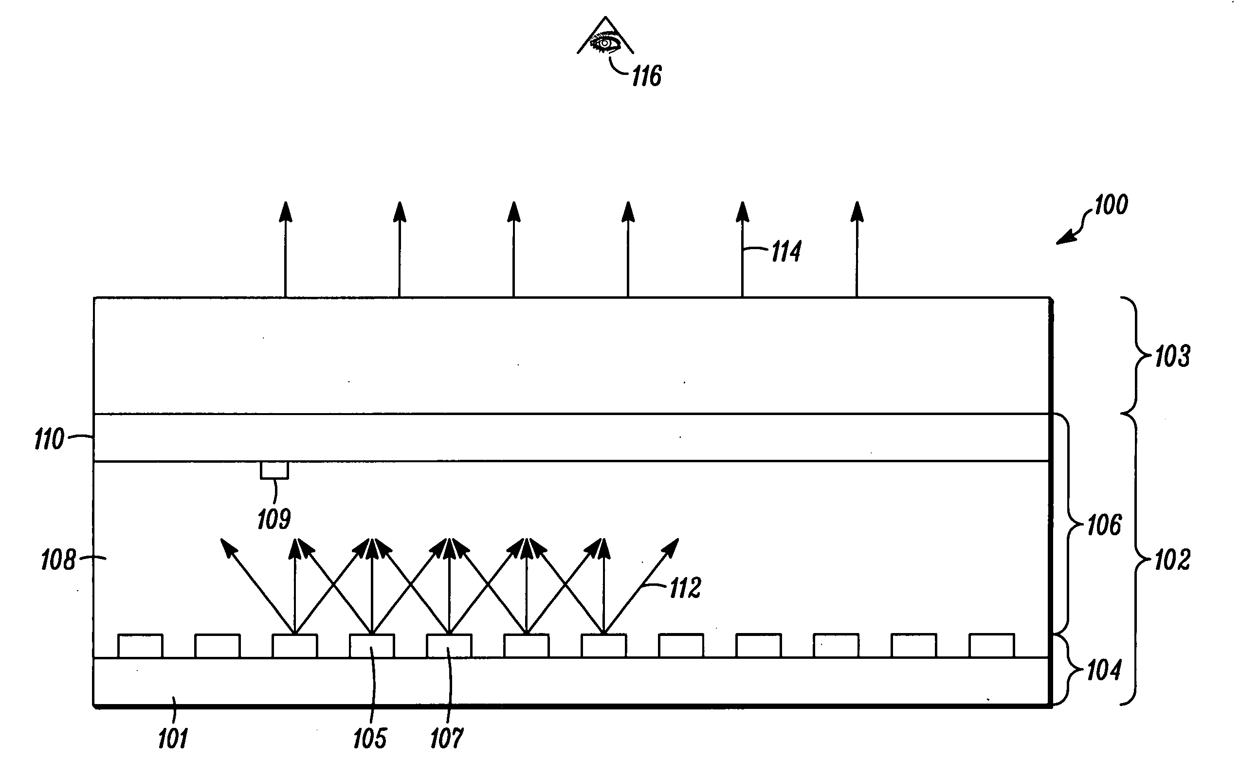
[0017]FIG. 1 is a simplified cross-sectional view of an exemplary embodiment of a backlit LCD display 100, for use, for example, as an avionics display. Backlit LCD display 100 comprises a backlight assembly 102 coupled to a LCD assembly 103. Backlight assembly 102 comprises a direct backlight 104 coupled to a light integration unit 106. In the exemplary embodiment of FIG. 1, the direct backlight 104 is known as a direct view illumination system because the illumination is provided directly behind the LCD assembly 103.

[0018] Direct backlight 104 comprises first white LEDs 105 having a first color temperature and second white LEDs 107 havi...


PUM


Abstract

A LCD display comprises a backlight assembly that includes a backlight substrate, one or more first white LEDs coupled to the backlight substrate and configured to produce a first light output, and one or more second white LEDs coupled to the backlight substrate and configured to produce a second light output. A light integration unit is coupled to the backlight assembly and configured to produce a combined output from the first light output and the second light output, the combined output having a desired luminance and chrominance. A LCD assembly is coupled to the light integration unit.

Description

FIELD OF THE INVENTION [0001] The present invention relates to the field of LCD displays, and more particularly, to a LED backlight system for LCD displays. BACKGROUND OF THE INVENTION [0002] Backlights are used in transmissive displays, such as liquid crystal displays (LCDs), to enhance user visibility under various conditions. The most common type of backlights for LCDs are fluorescent lamp backlights. Fluorescent lamp backlights, while effective in many applications, generally have a relatively high driving voltage. Additionally, it is difficult to provide dimming (i.e., variable luminance) and color alteration (i.e., variable chrominance) capabilities in fluorescent backlights. Also, compact fluorescent lamps are relatively fragile and the use of compact fluorescent lamps in backlight applications where mechanical ruggedness is important, such as avionics applications, can be problematic. [0003] Light emitting diode (LED) backlights have been developed in order to provide a back...

Claims


Application Information

Patent Timeline
Patent Type & Authority Applications(United States)
IPC IPC(8): F21V7/04
CPCG02B6/0028G02B6/0031G02F1/133609G02F1/133603G02B6/0068
Inventor HAIM, VICTORIA P.HAIM, ELIAS S.LARSON, BRENT D.DAVEY, DENNIS M.
Owner HONEYWELL INT INC
Learn More