Projection system and color wheel thereof
a projection system and color wheel technology, applied in the field of projection systems, can solve the problems of less than 100% decay of light transmission rate of light beam passing through the transparent filter, etc., to avoid vibration and noise, improve image brightness, and prevent the effect of light transmission ra
- Summary
- Abstract
- Description
- Claims
- Application Information
AI Technical Summary
Benefits of technology
Problems solved by technology
Method used
Image

Examples
first embodiment
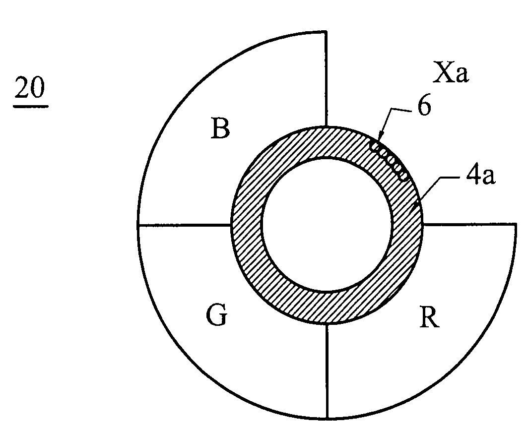
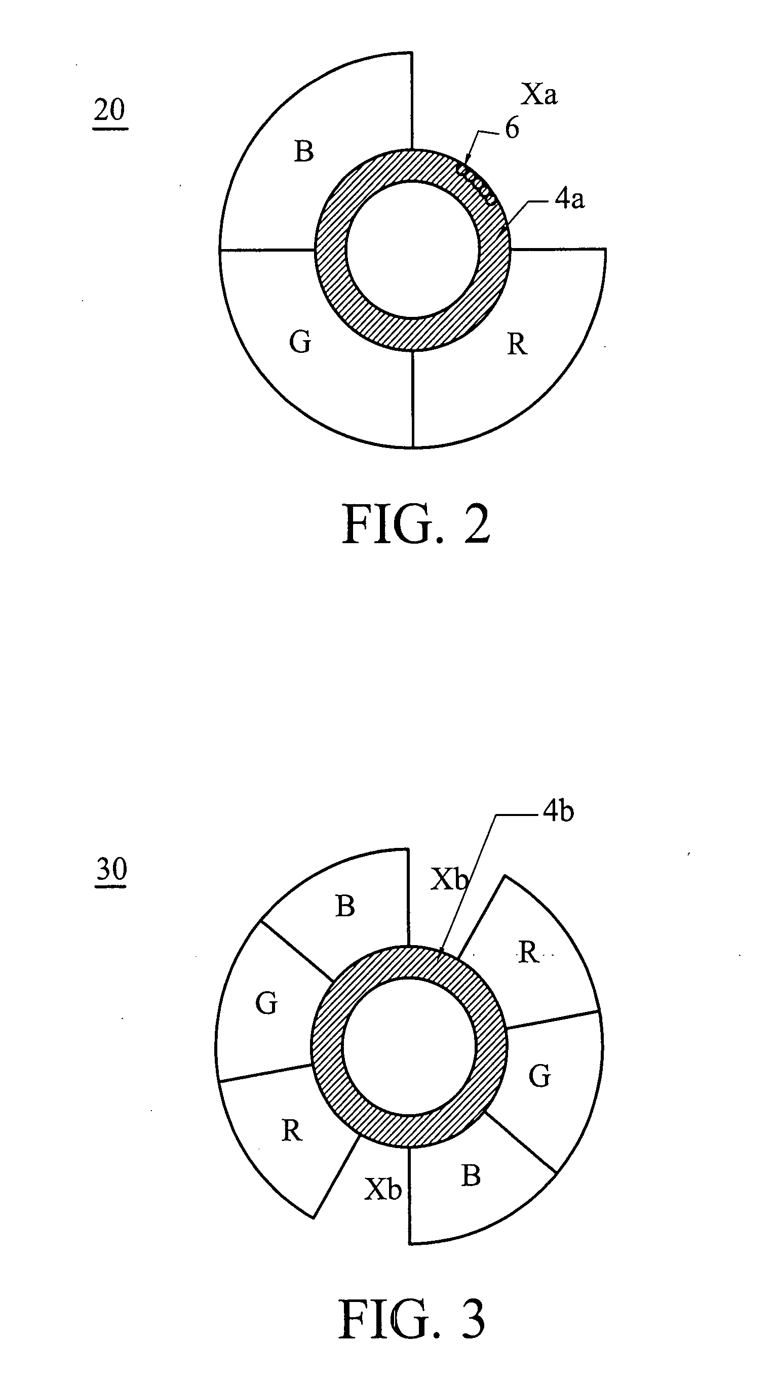
[0024]In FIG. 2, a color wheel 20 of the invention includes a carrier 4a, a plurality of color filters fixedly disposed around the carrier 4a to form at least one gap Xa, and a balancer 6 disposed at the carrier 4a corresponding to the gap Xa. The carrier 4a is centrally pivoted to the shaft of the motor so that the color wheel 20 can be driven by the motor. In this embodiment, the number of the color filters is three, including red, green and blue one, labeled by symbols “R”, “G” and “B”, respectively. The color filters are fixedly disposed around the peripheral of the carrier 4a, and the gap Xa is located between the red and blue color filters “R” and “B”.
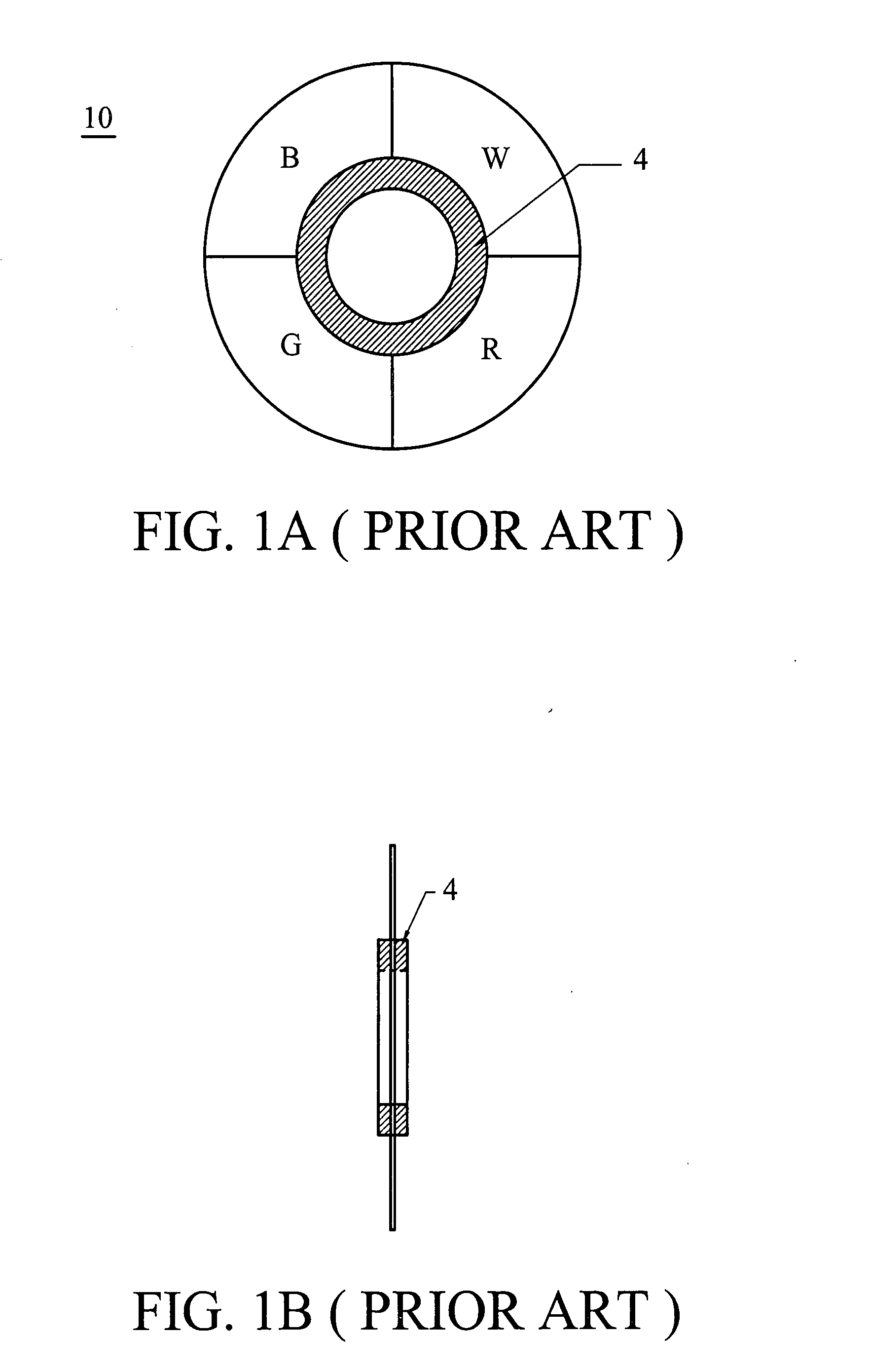
[0025]In comparison with FIG. 1A, it is understood that the color wheel 20 differs from the color wheel 10 of FIG. 1A in that the transparent filter “W” of the color wheel 10 is directly replaced by the gap Xa to reduce the loss of light transmission rate when the light beam pass through the transparent filter “W” of the color wh...
second embodiment
[0027]In FIG. 3, a color wheel 30 of the invention includes a carrier 4b and two sets of three-color filters “R”, “G” and “B” fixedly disposed around the carrier 4b at a peripheral thereof to form two corresponding gaps Xb, instead of the transparent filter “W” of the color wheel 10 of FIG. 1A. In this embodiment, the two corresponding gaps Xb have the same size. Note that the described balancer 4 or the like can be optionally eliminated if the corresponding gaps have the same size, and a moment couple can be formed therebetween to balance the rotational color wheel 30.
third embodiment
[0028]In FIG. 4, a color wheel 40 of the invention includes a carrier 4c and three spaced color filters “R”, “G” and “B” fixedly disposed around the carrier 4b at a peripheral thereof to symmetrically form three gaps Xc having a central line cl, and an angle φ is formed between the central lines cl of the gaps Xc with respect to a center of the carrier 4c, instead of the transparent filter “W” of the color wheel 10 of FIG. 1A. In this embodiment, the three gaps Xc have the same size, and the angle φ formed between two adjacent central lines cl is 120 degree. Note that the number of the gap Xc is not limited to the disclosed embodiment, and the gaps Xc can be asymmetrically arranged with respect to the center of the carrier 4c as a moment couple can be formed on the color wheel 40 to balance the rotational color wheel 30, such as the use of the described balancer 6.
PUM
 Abstract
Description
Claims
Application Information
 - R&D
- Intellectual Property
- Life Sciences
- Materials
- Tech Scout
- Unparalleled Data Quality
- Higher Quality Content
- 60% Fewer Hallucinations
Browse by: Latest US Patents, China's latest patents, Technical Efficacy Thesaurus, Application Domain, Technology Topic, Popular Technical Reports.
© 2025 PatSnap. All rights reserved.Legal|Privacy policy|Modern Slavery Act Transparency Statement|Sitemap|About US| Contact US: help@patsnap.com