
Water Treatment Apparatus

a technology of water treatment apparatus and water treatment system, which is applied in the direction of multi-stage water/sewage treatment, separation process, filtration separation, etc., can solve the problems of increasing the complexity of the installation process, and affecting the quality of water treatmen

Inactive Publication Date: 2007-11-15
KINETICO
View PDF19 Cites 15 Cited by
  • Summary
  • Abstract
  • Description
  • Claims
  • Application Information

AI Technical Summary

Benefits of technology

[0004] The present invention provides a new and improved method and apparatus for integrating a water treatment apparatus into an existing water distribution system.

Problems solved by technology

It can become even more complicated when auxiliary components, such as bypass valves, and auxiliary filters, need be plumbed as part of the installation.
It has been found that considerable installer time can be expended in creating the plumbing interconnections.
In some cases the plumbing connections are very complicated and costly and may compromise the ability to service the device in the future.

Method used


Image

  • Water Treatment Apparatus
  • Water Treatment Apparatus
  • Water Treatment Apparatus

Examples


Embodiment Construction

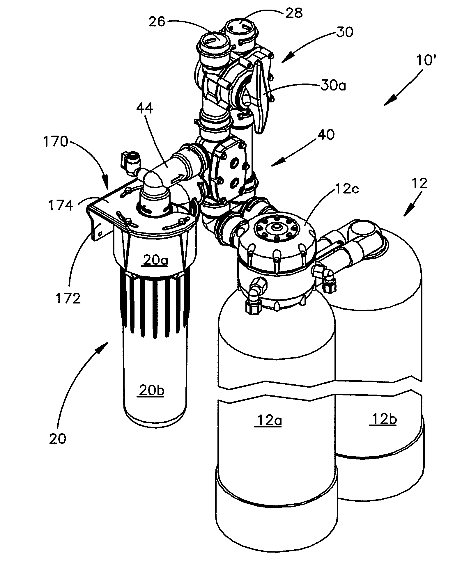
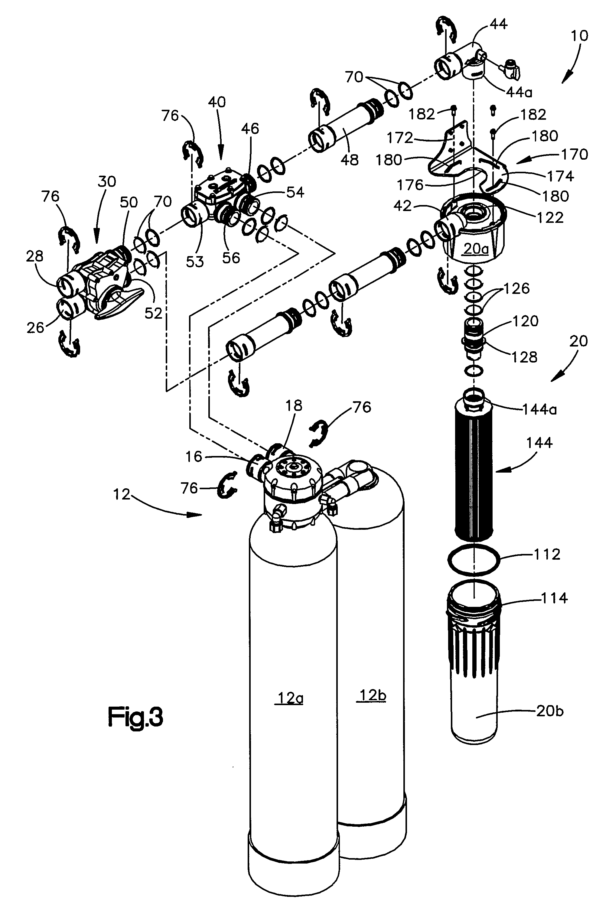
[0030]FIG. 1 illustrate one configuration of a water treatment apparatus 10 constructed in accordance with a preferred embodiment of the invention. In the illustrated embodiment, the overall apparatus includes a water treatment unit 12 which comprises a pair of tanks 12a, 12b interconnected by a control valve 12c. The water treatment unit 12 may take several forms and may for example, be a water softening unit such as disclosed in U.S. Pat. No. 4,298,025, a water deionizer disclosed in U.S. Pat. No. 4,427,549 and / or a water filtering apparatus such as that disclosed in U.S. Pat. No. 4,693,814. All of the above-mentioned patents are hereby incorporated by reference. The control valve 12c as more fully discussed and explained in one or more of the above-identified patents, controls the communication of water to be treated from a control valve inlet 16 to one or both of the tanks 12a, 12b. The control valve 12c delivers treated water that passes through one or both treatment tanks to a...


PUM

PropertyMeasurementUnit
structureaaaaaaaaaa
water pressureaaaaaaaaaa
pressureaaaaaaaaaa

Abstract

A water treatment apparatus which facilitates the installation of a water treatment unit and prefilter into an existing plumbing system. The apparatus includes a bypass valve interconnected with a prefilter and water treatment unit using a connection box. The fittings and orientations are chosen for the components so that various configurations and orientations can be easily accommodated and with a minimum of parts. The apparatus eliminates the need for fabricating conduit segments, etc. at the installation site. The apparatus for connecting a water treatment unit to a water distribution system includes a control valve having spaced apart inlet and outlet ports and a connection module defining first and second flow passages. The first flow passage extends between first and second external ports and the second flow passage extends between third and fourth external ports. The first and third external ports are arranged and configured to correspond to the configuration and. spacing of the control valve inlet and outlet ports. A filter unit includes inlet and outlet ports that are configured and oriented to correspond to the configuration and spacing of the control valve inlet and outlet ports. The filter includes a filter head and a sump releasably coupled to the head. The sump at least partially defines a filter chamber containing a replaceable filter element. A cup seal seals the interface between the head and the sump and includes a sealing lip that is urgent to sealing engagement with a filter chamber wall by water pressure. At predetermined lower water pressures the sealing engagement between the seal and the chamber wall is reduced to enable the sump to be decoupled using hand manipulation. At least one of the filter ports is swivelly connected to the head to enable the orientation of the port to be changed.

Description

TECHNICAL FIELD [0001] The present invention relates generally to fluid treatment systems and, in particular, to a method and apparatus that facilitates installation of a fluid treatment system that includes a fluid treatment unit and prefilter. BACKGROUND ART [0002] It has become common, especially in some areas of the country, to use water treatment devices to filter or treat all or portions of the water used by a household or business. In the case of household water supplies, treatment devices for softening water, removing mineral content, and other impurities, are becoming more and more commonplace. In addition, treatment devices, such as reverse osmosis units, are becoming popular and operate to filter or purify a portion of the water supply that is intended to be consumed. [0003] When these types of water treatment devices, i.e., water softeners, are installed, the installer must fabricate plumbing connections between the existing household plumbing conduits and the device. It...

Claims


Application Information

Patent Timeline
Patent Type & Authority Applications(United States)
IPC IPC(8): B01D21/30B01D27/10B01D29/88C02F1/44
CPCB01D2201/291B01D2201/302B01D2201/4015C02F1/001E03B7/074C02F1/42C02F1/441C02F9/005C02F1/008C02F9/20
Inventor JORDAN, GEORGE R.HOOPES, STEVEN M.
Owner KINETICO
Learn More