Percutaneous dilation apparatus

a dilation apparatus and percutaneous technology, applied in the field of medical devices, can solve the problems of increasing the number of dilation exchanges, affecting the effect of dilation, and affecting the effect of dilation, and achieve the effect of enlargement of the penetration

Inactive Publication Date: 2007-11-01
KIMBERLY-CLARK WORLDWIDE INC
View PDF16 Cites 9 Cited by
  • Summary
  • Abstract
  • Description
  • Claims
  • Application Information

AI Technical Summary

Benefits of technology

[0009] In other embodiments, the apparatus may contain a plurality of cylindrical dilator segments graduated in size from smaller to larger, and concentrically arranged about the dilator probe and the next smaller dilator segment. Each segment would be engaged sequentially by the catch and moved toward the distal end to enable enlargement of the penetration.

Problems solved by technology

While this technique is reasonably effective for placement of relatively small devices, e.g., catheters to about 6 French [1 French (F) is equal to 0.079 inch diameter], larger dilations require increasing numbers of dilator exchanges and can be extremely time consuming.
Moreover, the body structures that are being penetrated frequently comprise relatively flaccid membranes or walls so that penetration with larger dilators may cause fascial detachment, i.e., the invagination and separation of the membrane or wall from surrounding tissue structures.
Such problems may be exacerbated when the organ, tissue, or cavity being penetrated is diseased so that the membranes or walls are thickened or toughened and resistant to penetration by the dilator which axially engages the tissue.
While this approach is generally successful, it requires a separate puncture for each anchor and the subsequent suturing of each anchor in place.
The technique is therefore relatively time consuming, costly, and potentially subjects the patient to greater discomfort.
An additional problem with the use of successively larger dilators, either with or without use of an anchoring technique, is the leakage of body fluids and substances through the penetration which is being enlarged.
Transperitoneal access proceeds through an unattached wall of the gallbladder and increases the likelihood of bile leakage into the peritoneal.
While transperitoneal access might otherwise be preferred for a number of reasons, e.g., it avoids potential damage to the liver, it is contraindicated by the difficulty in penetrating the unattached wall of the gallbladder and the greater risk of bile leakage associated with conventional dilation techniques.

Method used


Image

  • Percutaneous dilation apparatus
  • Percutaneous dilation apparatus
  • Percutaneous dilation apparatus

Examples


Embodiment Construction

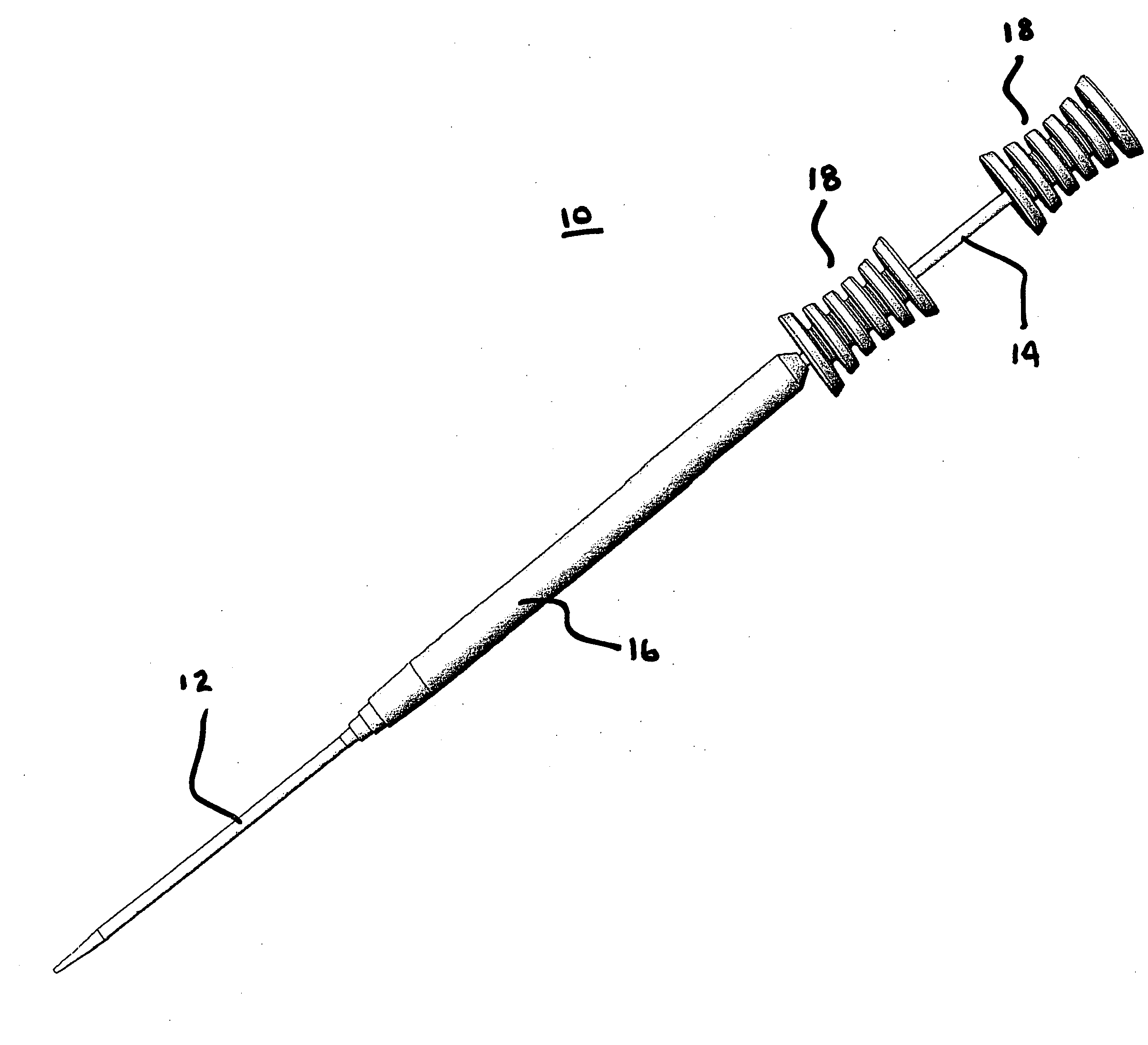
[0020] The present invention is useful for forming and enlarging percutaneous penetrations to a variety of target locations within a patient's body for a multiplicity of purposes. The initial penetration will be very small, usually being below about 7 F, more usually being below about 3 F, and frequently being below about 20 GA (gauge; 0.035 in). The penetration will subsequently be enlarged to a desired final size, usually having a final diameter in the range from about 10 French (F) to about 30 F, typically being from about 12 F to 28 F, and usually being from about 14 F to 24 F, with the present invention being particularly useful for the formation of larger diameter penetrations.

[0021] The purpose of the penetration may be for drainage, intraorgan drug administration, perfusion, aspiration, or the like, but will usually be for the introduction of a relatively large surgical instrument or working catheter, such as those intended for least invasive surgical procedures. Such proce...


PUM


Abstract

A percutaneous dilation apparatus is shown. The apparatus is useful for forming and enlarging percutaneous penetrations to a variety of target locations within a patient's body for multiple purposes. The apparatus includes an at least one dilator segment, a dilator probe, and a mechanism for moving each dilator segment along the dilator probe so as to place it within the penetration thereby dilating the penetration.

Description

BACKGROUND OF THE INVENTION [0001] The present invention relates generally to a medical device for facilitating the percutaneous access of a body lumen and, more particularly, it relates to the construction and use of a dilator tool or dilation apparatus which enables the sequential radial dilation of a tissue opening to create larger diameter working channels into the body lumen. [0002] Modern medicine frequently requires percutaneous access to hollow body organs, tissue, cavities, and the like. In the case of “least or minimally invasive” surgical procedures, such access is usually provided by inserting a suitable cannula, instrument, tube, or the like, through a small access hole. The initial access is usually created by piercing the skin and any intermediate body structures with a needle or trocar. The initial puncture, however, is usually very small so that the needle or trocar can achieve the desired penetration without excessive damage to tissue. It is therefore necessary for...

Claims


Application Information

Patent Timeline
Patent Type & Authority Applications(United States)
IPC IPC(8): A61M29/00
CPCA61B19/24A61M2025/0687A61M2025/0004A61M29/00A61B90/02
Inventor MCMICHAEL, DONALD J.BACON, JOHN K.ROTELLA, JOHN A.PETERSON, KRISTY
Owner KIMBERLY-CLARK WORLDWIDE INC
Why Eureka
Try Eureka