
Rack mountable power distribution apparatus

a power distribution apparatus and rack mount technology, applied in electrical equipment, substation/switching arrangement details, ac network circuit arrangement, etc., can solve the problems of insufficient power strip, inconvenient re-cabling of electrical output circuits, and inconvenient operation, etc., to achieve cost saving, compact design, and cost effective

Inactive Publication Date: 2007-11-01
S & S POWER ENG
View PDF28 Cites 27 Cited by
  • Summary
  • Abstract
  • Description
  • Claims
  • Application Information

AI Technical Summary

Benefits of technology

"The present invention is a new electrical power distribution apparatus that is compact, cost-effective, and labor-saving. It is designed to meet the needs of both large and small facilities. The apparatus is easy to install and maintain, and it can be hardwired or connected through receptacles for both direct and remote power distribution. It is also adaptable for use with single-phase or three-phase power. The apparatus includes a housing and an electrical power input assembly, as well as multiple output assemblies that can be hardwired or receptacle circuits. The system also includes a transformer for safe and effective power distribution. The invention provides flexibility and versatility in meeting the electrical power needs of various facilities."

Problems solved by technology

However, electrical power distribution units and systems for supplying power to electrical devices, such as computers and other critical equipment, in a building or other facility have remained bulky and sometimes difficult to work with.
However, in many cases, a power strip is not appropriate or sufficient for large scale changes in electrical needs, or for accommodating additional pieces of critical equipment which requires hard-wired connections to the power source.
The process of re-cabling electrical output circuits from the PDU, for example, to more strategic locations within the facility, is a costly, labor intensive task, which typically requires the work of outside contractors who specialize in electrical cabling and rewiring.
Because of the inherent difficulty of accessing a specific wire or cable from the numerous, and sometimes tangled masses of cables and wires concealed within walls or floors of the facility, obsolete and unusable cables are often left in place adding to the confusion and difficulty of maintaining or controlling such wiring.

Method used


Image

  • Rack mountable power distribution apparatus
  • Rack mountable power distribution apparatus
  • Rack mountable power distribution apparatus

Examples


Embodiment Construction

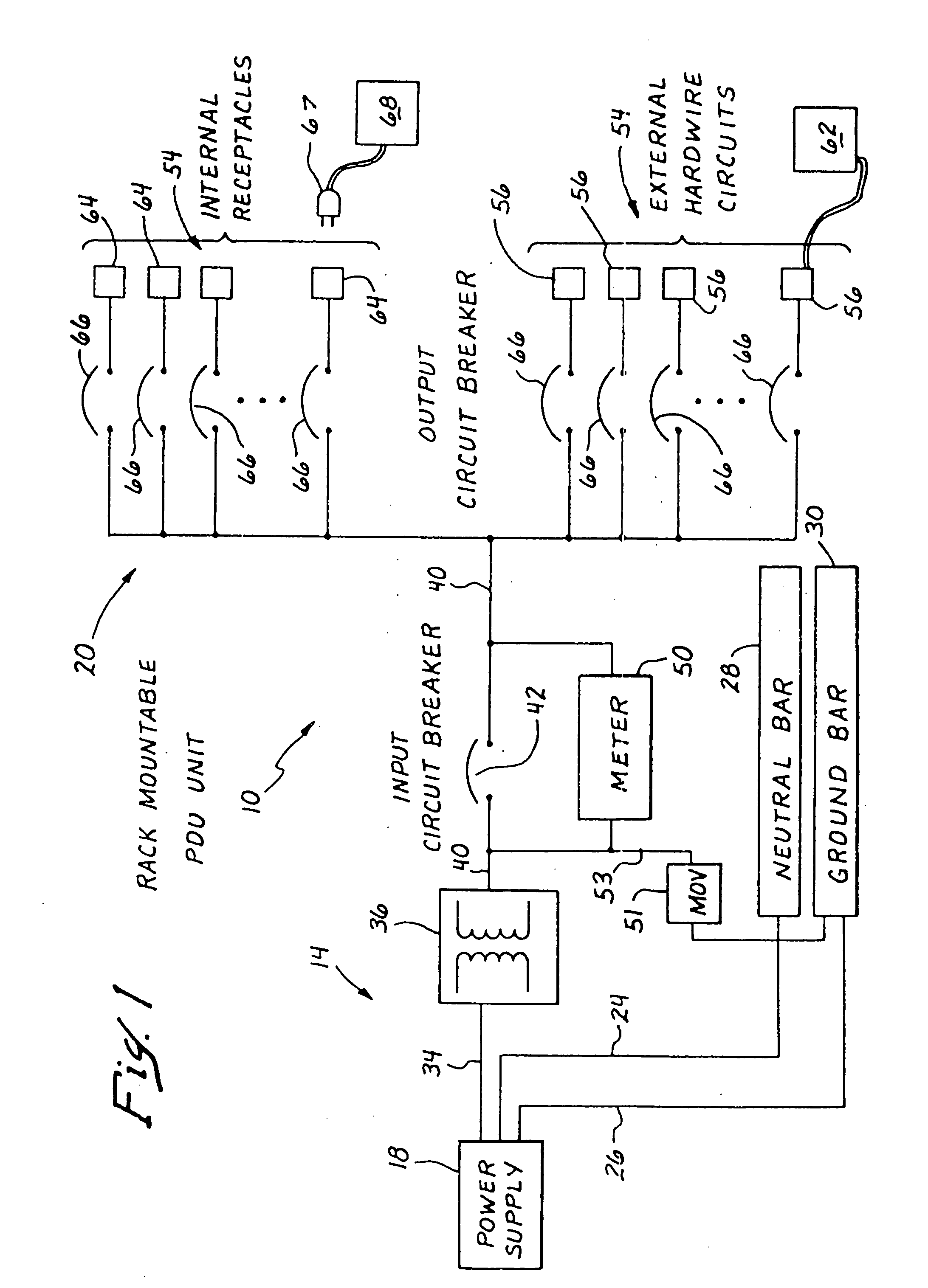
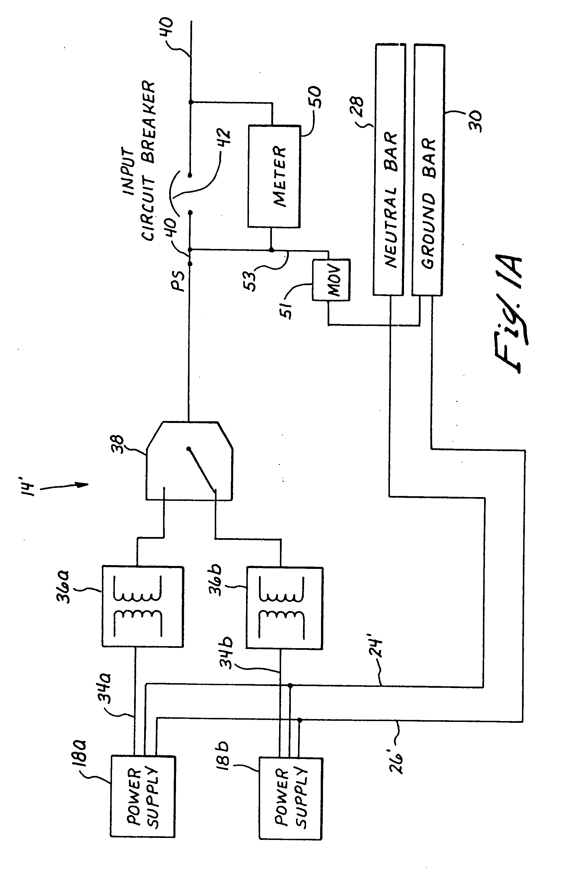
[0026] Turning now to FIG. 1, a power distribution apparatus 10, in accordance with the invention is represented by a block circuit diagram. The apparatus 10 generally comprises an electrical power input assembly, represented generally at 14, adapted to receive power from an uninterruptible or substantially constant electrical power source or supply 18, and a plurality of electrical power output assemblies, represented generally at 20, adapted to receive and distribute electrical power from the input assembly 14. The power supply 18 may be provided by a commercial power source, for example, a single phase system or three phase system. Neutral and ground lines 24 and 26, respectively, are shown connecting the power supply 18 to a neutral bus bar 28 and a ground bus bar 30 respectively, as is conventional.

[0027] Electrical power through power input line 34 is passed through a transformer 36, of conventional design, adapted to be in electrical communication with both the electrical po...


PUM


Abstract

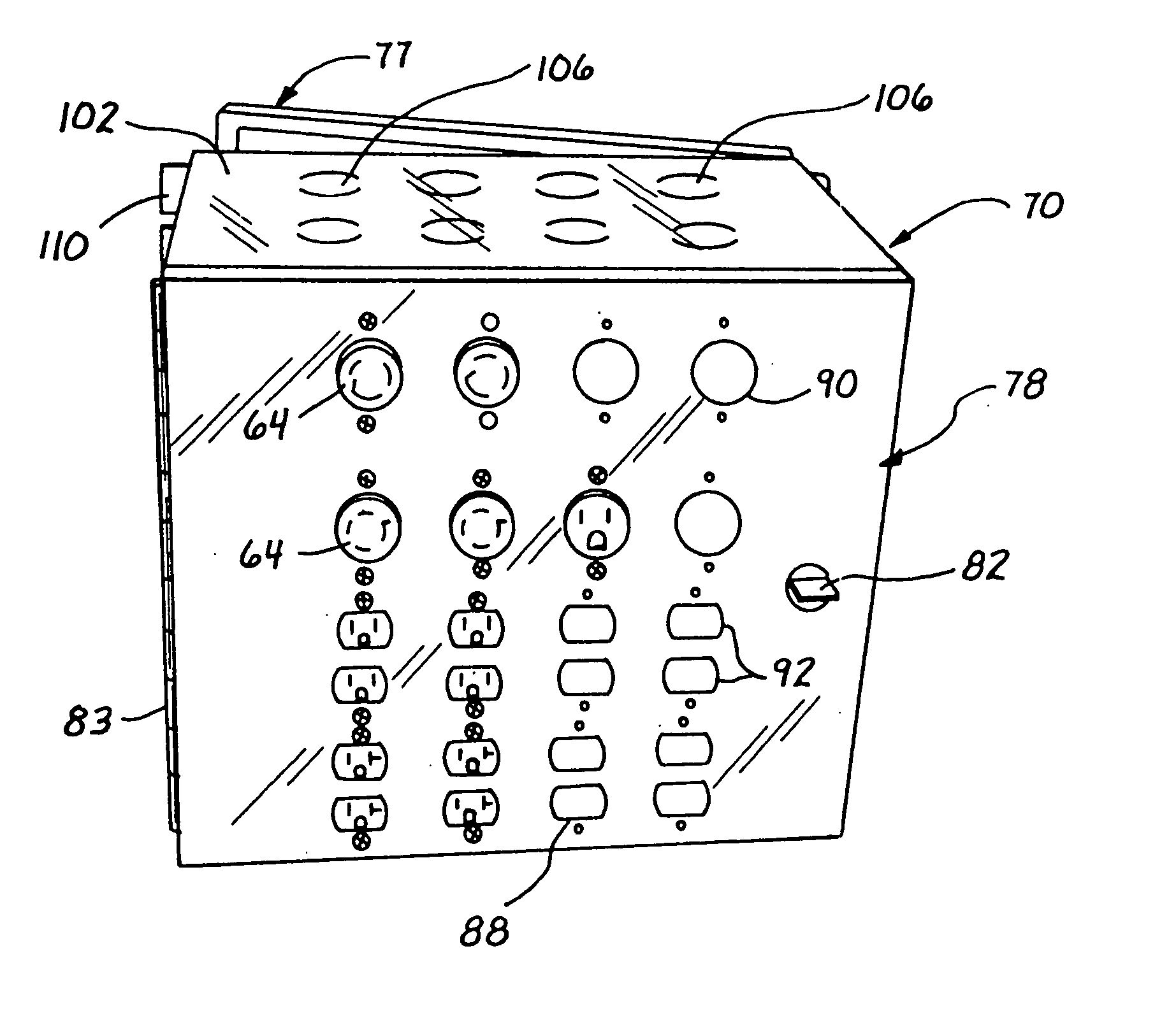
Power distribution apparatus include a rack mountable housing, an electrical power input assembly and an electrical power output assembly including a plurality of external circuits adapted for hardwired to remote equipment and a plurality of internal circuits each adapted to receive a plug of electrical equipment and to provide power thereto. The plurality of internal circuits may include differently configured receptacles adapted to receive differently configured plugs.

Description

RELATED APPLICATIONS [0001] This application is a continuation of U.S. Ser. No. 09 / 730,689, filed Dec. 6, 2000, which is a continuation-in-part of U.S. patent application Ser. No. 09 / 469,978 filed Dec. 21, 1999, now U.S. Pat. No. 6,608,406, the disclosure of each of which is hereby incorporated in its entirety herein by this reference.BACKGROUND OF THE INVENTION [0002] The present invention generally relates to electrical power distribution apparatus, and more particularly relates to low cost, multi-function, rack mountable electrical power distribution apparatus and systems. [0003] Research and development of computer technology has continually produced smaller and more compact systems. However, electrical power distribution units and systems for supplying power to electrical devices, such as computers and other critical equipment, in a building or other facility have remained bulky and sometimes difficult to work with. [0004] Conventionally, electrical power coming into a facility...

Claims


Application Information

Patent Timeline
Patent Type & Authority Applications(United States)
IPC IPC(8): H02B1/20H02B1/24H02B1/42H02J3/00
CPCH02B1/24H02J3/00H02B1/42
Inventor BERSIEK, SHAMEL A.
Owner S & S POWER ENG
Learn More