
Ablation probe with ribbed insulated sheath

a technology of insulating sheath and ablation probe, which is applied in the direction of medical science, surgery, surgical instrument details, etc., can solve the problems of compromising integrity, creating a larger lesion size, and reducing the chance of healthy tissue being inadvertently ablated, so as to minimize the chance of healthy tissue being ablated

Inactive Publication Date: 2007-10-25
BOSTON SCI SCIMED INC
View PDF17 Cites 41 Cited by
  • Summary
  • Abstract
  • Description
  • Claims
  • Application Information

AI Technical Summary

Benefits of technology

The present invention relates to a tissue ablation probe that can be used to ablate tissue. The probe has an electrically insulative sheath with ribs that allow for easy delivery through a tightly toleranced delivery device. The sheath can be removably disposed within a cannula, and the probe can be used in a method to ablate tissue by introducing the probe through the cannula and ablating the tissue region with the electrodes. The probe can also be used in a tissue ablation assembly that includes a cannula and a tissue ablation probe, where the probe has depressions that cooperate with the inner surface of the cannula to form fluid lumens. The fluid can be infused through the lumens into contact with the tissue region to further treat it. The technical effects of the invention include improved delivery and efficient fluid infusion for tissue ablation.

Problems solved by technology

Because the size of tissue coagulation created from a single electrode, and to a lesser extent a multiple electrode array, has been limited by heat dispersion, it is known to introduce an electrically conductive fluid, such as saline, into targeted tissue to increase the tissue conductivity, thereby creating a larger lesion size.
It has been shown that the introduction of saline into targeted tissue during an ablation procedure increases the tissue conductivity, thereby creating a larger lesion size.
However, RF ablation probes are often introduced through other tightly toleranced devices that may compromise the integrity of the thinly layered insulation, thereby inadvertently exposing healthy tissue to RF energy.
As a result, the attending physician will either have to replace the probe with a new one or risk ablating healthy tissue.
However, equipping the cannula with lumens will ultimately increase its profile, thereby increasing the pain and tissue trauma associated with the percutaneous introduction of the cannula into the patient.
However, in the case of LeVeen Needle Electrodes™, every diminutive amount of space inside the cannula of the RF probe must be utilized by the needle electrodes, and therefore, it is difficult to design lumens within such probes.

Method used


Image

  • Ablation probe with ribbed insulated sheath
  • Ablation probe with ribbed insulated sheath
  • Ablation probe with ribbed insulated sheath

Examples


Embodiment Construction

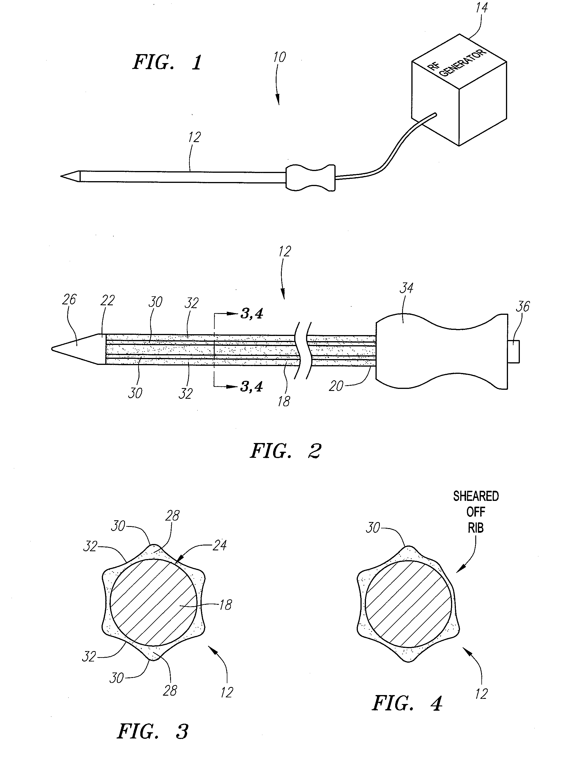
[0031] Referring to FIG. 1, a tissue ablation system 10 constructed in accordance with one embodiment of the present inventions, will now be described. The tissue ablation system 10 generally comprises an ablation probe 12 configured for introduction into the body of a patient for ablative treatment of target tissue, a source of ablation energy, and in particular a radio frequency (RF) generator 14, and a cable 16 electrically connecting the ablation probe 12 to the RF generator 14.

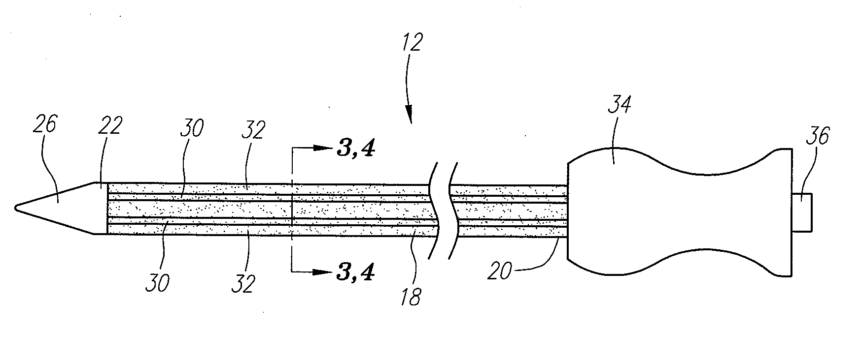
[0032] Referring now to FIG. 2, the ablation probe 12 will be described in further detail. The ablation probe 12 comprises an elongated, probe shaft 18 having a proximal end 20 and a distal end 22. The probe shaft 18 is composed of an electrically conductive material, such as stainless steel. The probe shaft 18 has a suitable length, typically in the range from 5 cm to 30 cm, preferably from 10 cm to 25 cm, and an outer diameter consistent with its intended use, typically being from 0.7 mm to 5 mm, usual...


PUM


Abstract

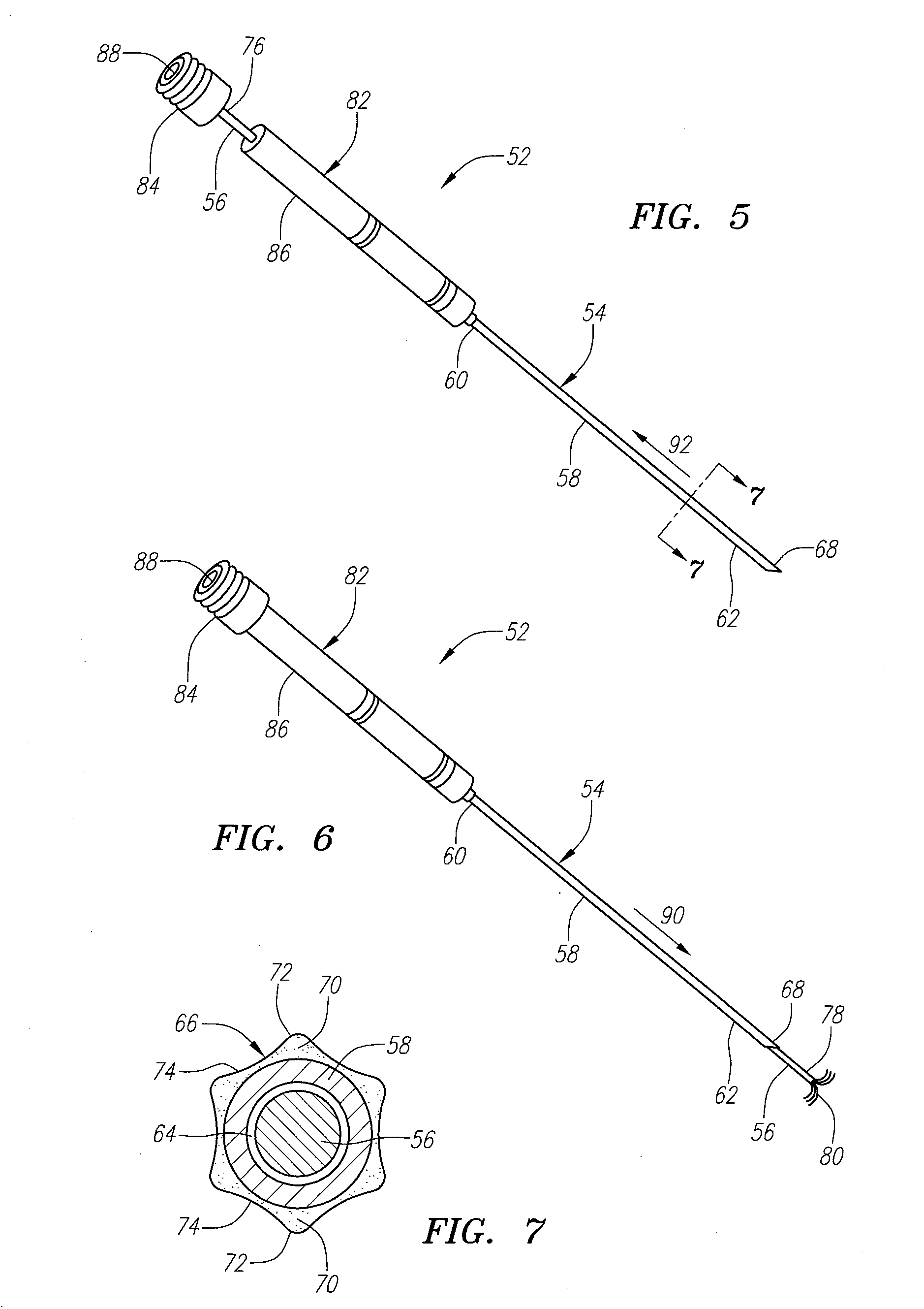
A tissue ablation probe comprises an electrically conductive probe shaft, at least one electrode, and an electrically insulative sheath disposed on the probe shaft. The insulative sheath has thickened regions forming alternating ribs and depressions that longitudinally extend along the probe shaft. The ribs allow the ablation probe to be delivered through a tightly toleranced delivery device. While the ribs may shear off during the delivery process, the underlying probe shaft will remain covered by the remaining portion of the insulative sheath. The tissue ablation probe may be used in a tissue ablation assembly that additionally comprises a delivery cannula having a lumen in which the tissue ablation probe may be removably disposed. In this case, the sheath has an outer periphery having a size substantially the same as the diameter of the lumen, so that the inner surface of the delivery cannula cooperates with the depressions to create lumens that longitudinally extend within the cannula.

Description

FIELD OF THE INVENTION [0001] The field of the invention relates generally to the structure and use of radio frequency (RF) ablation probes for the treatment of tissue. BACKGROUND OF THE INVENTION [0002] The delivery of radio frequency (RF) energy to target regions within solid tissue is known for a variety of purposes of particular interest to the present invention. In one particular application, RF energy may be delivered to diseased regions (e.g., tumors) for the purpose of ablating predictable volumes of tissue with minimal patient trauma. [0003] RF ablation of tumors is currently performed using one of two core technologies. The first technology uses a single needle electrode, which when attached to a RF generator, emits RF energy from an exposed, uninsulated portion of the electrode. The second technology utilizes multiple needle electrodes, which have been designed for the treatment and necrosis of tumors in the liver and other solid tissues. U.S. Pat. No. 6,379,353 discloses...

Claims


Application Information

Patent Timeline
Patent Type & Authority Applications(United States)
IPC IPC(8): A61B18/14
CPCA61B18/1477A61B18/1482A61B2018/1425A61B2018/00166A61B2018/00577A61B2018/00083A61B2017/00845
Inventor FERNALD, KATHLEENRIOUX, ROBERT F.
Owner BOSTON SCI SCIMED INC
Learn More