
System and method for image-based interventional device tracking and scan plane guidance

Active Publication Date: 2007-10-25
THE JOHN HOPKINS UNIV SCHOOL OF MEDICINE +1
View PDF4 Cites 42 Cited by
  • Summary
  • Abstract
  • Description
  • Claims
  • Application Information

AI Technical Summary

Problems solved by technology

Such methods are inconvenient for doctors and have slow response times to device movement because multiple images at various angles must all be continually refreshed.
The drawbacks of this method are that embedding micro-coils in medical implements constrains their geometry and mechanical properties when precision is important.
While increasing the number of coils used improves the signal received, reducing the number of coils to allow flexibility in device geometry may result in insufficient localizing information.
Such imprecision in either form is undesirable for procedures that require tracking of multiple points and precise prediction and display of device response to user interaction.
Such techniques also impose mechanical limitations on devices—if the lumen is filled with a contrast agent, it can't be used for additional device or substance delivery which may be essential to the procedure.
However, while these active antennas, which do not utilize embedded RF coils, can be used for imaging and imaging-based tracking methods, signals from these antennas are not generally usable to determine the location of a device within a body.
Some methods exist wherein a combination of continuous active antennas and RF localizing coils are employed, but no method is presently known in which an entire or continuous length of an interventional device can be imaged and localized, without the use of embedded RF localizing coils.
This same problem of localization also exists for passive devices, such as gadolinium filled catheters, where an extended portion of the device can be visualized but not localized.
Inherent to most current visualizing and tracking methods is the inconvenience of lost depth information.
That is, depth information is generally lost in MR images of interventional devices (acquired by any of the above-mentioned techniques), causing a sometimes misleading device appearance.
Some adaptations have been developed to deal with these issues, but still present drawbacks.
However, such methods are not intended for, and do not provide, guidance of an interventional device for manipulation during a procedure.
That is, the MR acquisition scan plane is not adjusted to track the interventional device or aid in interventional device placement.

Method used

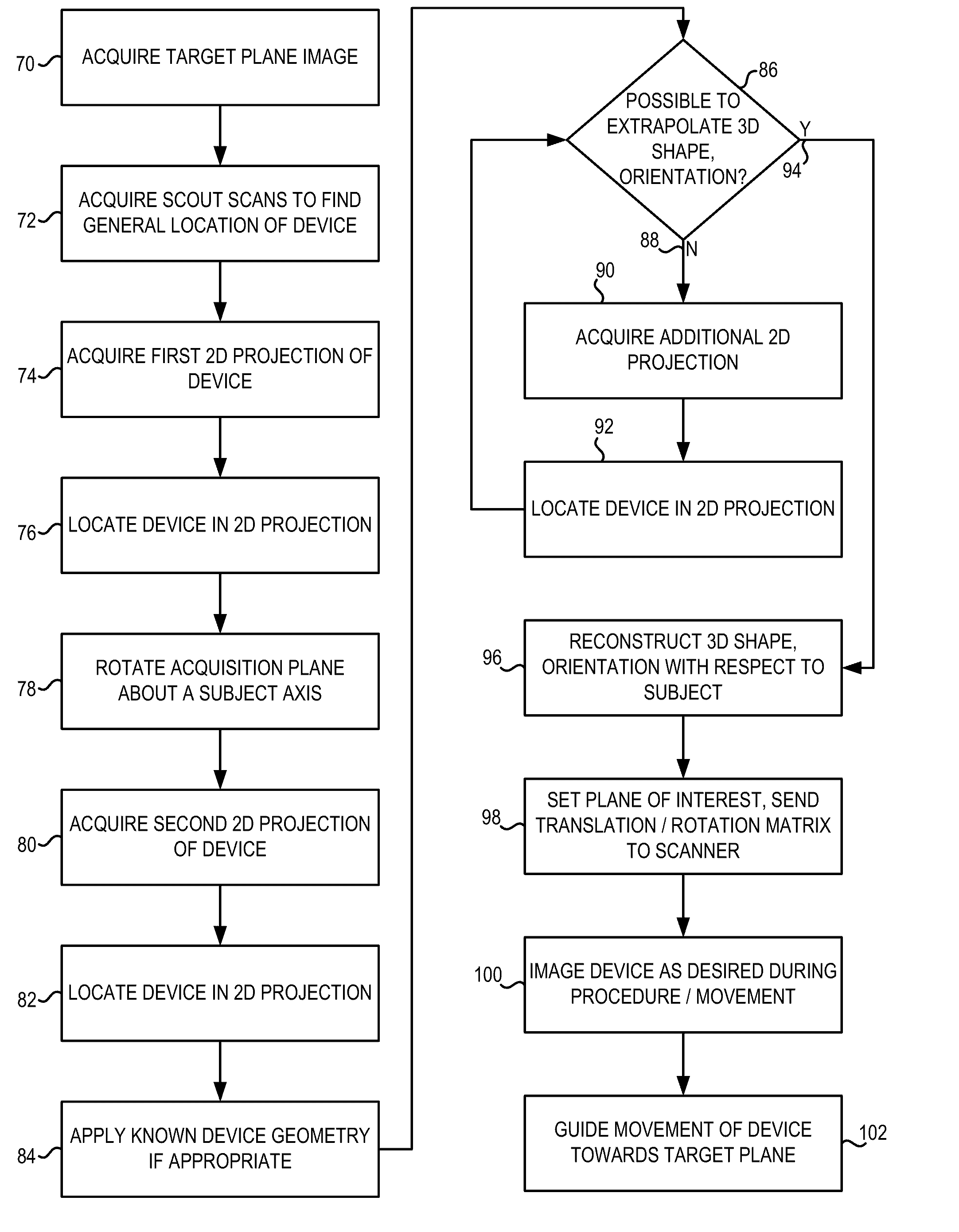
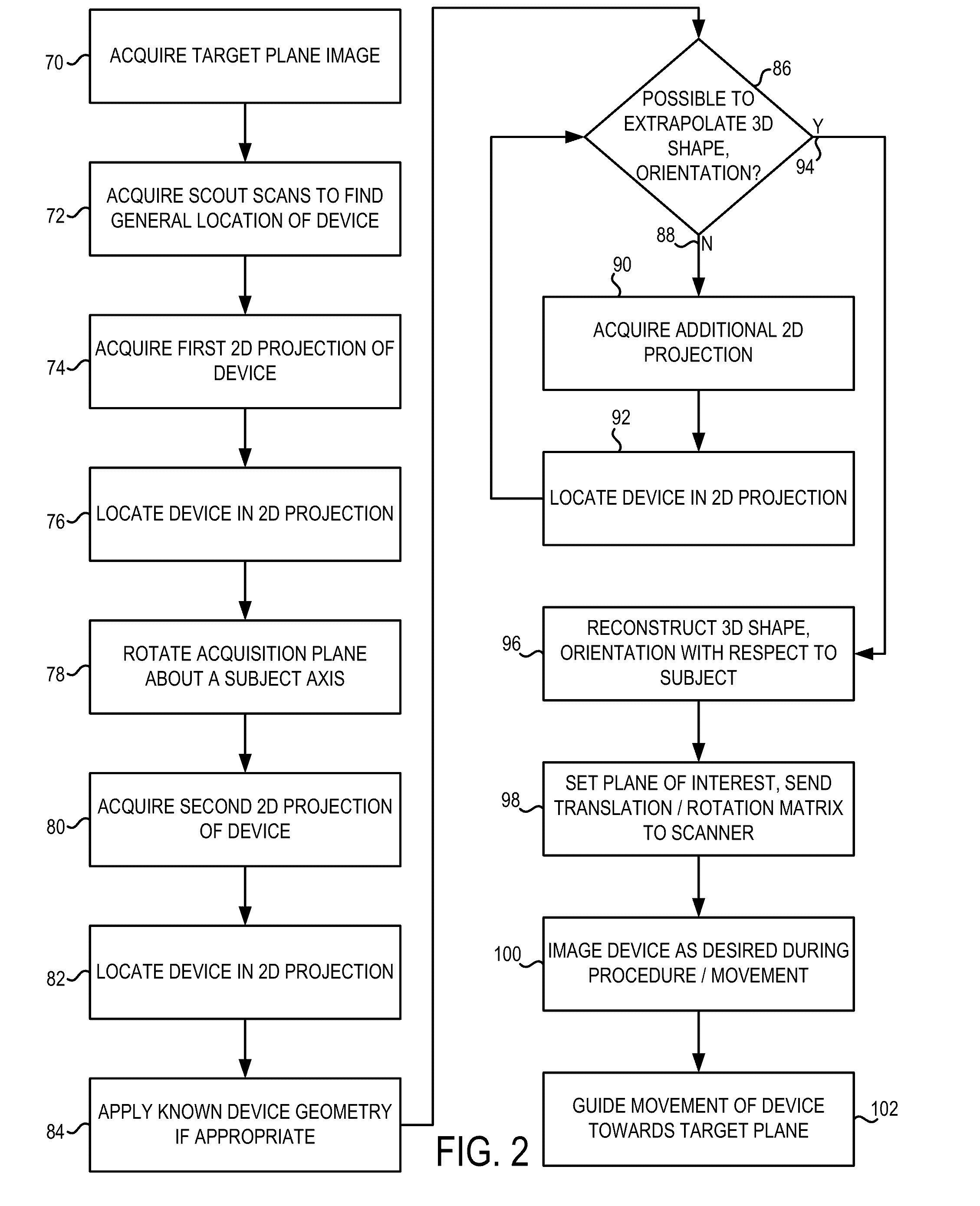

Image

  • System and method for image-based interventional device tracking and scan plane guidance
  • System and method for image-based interventional device tracking and scan plane guidance
  • System and method for image-based interventional device tracking and scan plane guidance

Examples


Embodiment Construction

[0032]A system and method of the present invention are hereinafter described that is capable of locating, and determining a shape and an orientation of implements used in interventional or invasive procedures. Though the present invention finds particular utility in tracking particular types of interventional devices for medical procedures, it is recognized that the present invention also encompasses a broad class of contrast mechanisms, recognition methods, devices, and procedures. This also includes non-medical procedures, and those involving the use of implements with negative MR contrast.

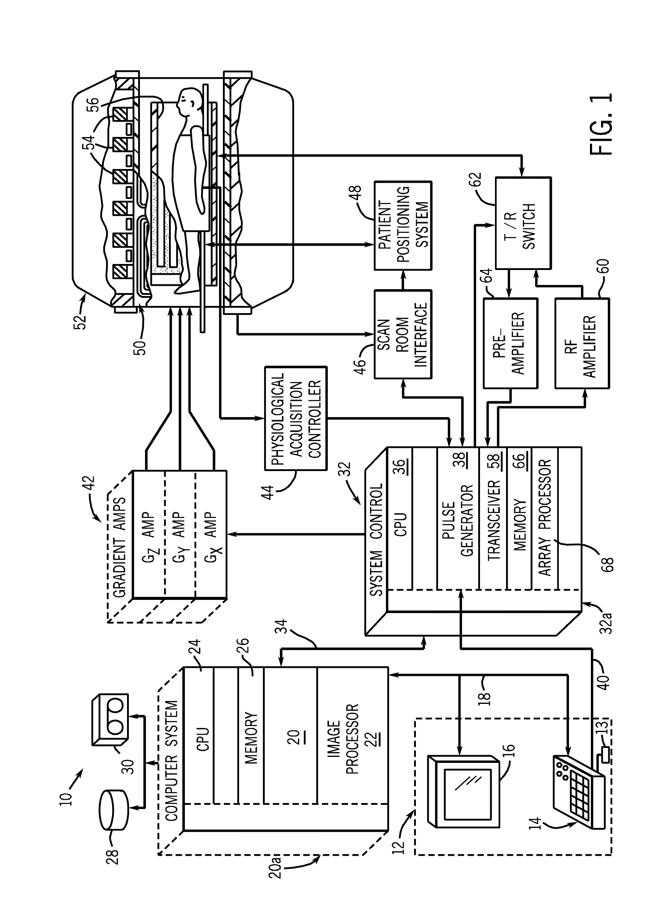
[0033]Referring to FIG. 1, the major components of a preferred magnetic resonance imaging (MRI) system 10 incorporating the present invention are shown. The operation of the system is controlled from an operator console 12 which includes a keyboard or other input device 13, a control panel 14, and a display screen 16. The console 12 communicates through a link 18 with a separate computer system ...


PUM


Abstract

An MR system and method for tracking a device of an interventional procedure within a scan subject is disclosed. At least two MR projections of the device are acquired, from which 3D coordinates of the device are determined. Subsequent image acquisition is adjusted with respect to the coordinates of the device to guide movement thereof towards target anatomy. The present system and method provide the ability to locate and visualize continuous portions of an interventional device in 3D, and do not require the use of embedded RF localizing coils.

Description

CROSS-REFERENCE TO RELATED APPLICATION[0001]The present invention claims the benefit of U.S. provisional application Ser. No. 60 / 793,394, filed Apr. 20, 2006, incorporated herein by reference.BACKGROUND OF THE INVENTION[0002]The present invention relates generally to MR imaging and, more particularly, to a system and method for tracking and visualizing interventional devices, such as catheters, via MR imaging to orient and guide real-time procedures without the need for localizing or embedded RF coils.[0003]When a substance such as human tissue is subjected to a uniform magnetic field (polarizing field B0), the individual magnetic moments of the spins in the tissue attempt to align with this polarizing field, but precess about it in random order at their characteristic Larmor frequency. If the substance, or tissue, is subjected to a magnetic field (excitation field B1) which is in the x-y plane and which is near the Larmor frequency, the net aligned moment, or “longitudinal magnetiz...

Claims


Application Information

Patent Timeline
IPC IPC(8): A61B5/05
CPCA61B5/055A61B19/5244A61B2019/5236A61B2019/5251A61B2019/5295G01R33/5608G01R33/34084G01R33/4833G01R33/543G01R33/546G01R33/287A61B5/0037A61B2090/367A61B34/20A61B2090/374A61B2034/2051
Inventor AKSIT, PELINSATHYANARAYANA, SHASHANKSOLAIYAPPAN, MEIYAPPANATALAR, ERGIN
Owner THE JOHN HOPKINS UNIV SCHOOL OF MEDICINE
Learn More