
Place-Status Management System, Radio Tag Reader, and Managing Apparatus

a management system and radio tag technology, applied in the direction of burglar alarm mechanical actuation, using reradiation, instruments, etc., can solve the problems of increasing cost, inability to determine which specific place is empty, and all parking places cannot be covered, so as to achieve low cost, low cost, and optional enlargement or narrowing of communication area

Inactive Publication Date: 2007-10-25
MITSUBISHI ELECTRIC CORP
View PDF12 Cites 26 Cited by
  • Summary
  • Abstract
  • Description
  • Claims
  • Application Information

AI Technical Summary

Benefits of technology

[0007] The present invention has been made to solve the above problems, and an object of the invention is to provide a place-status management system that can quickly obtain the state of whether there is an object or a person in a predetermined place such as a parking lot at low cost, and a radio tag reader and a managing apparatus used for the place-status management system. MEANS FOR SOLVING PROBLEM
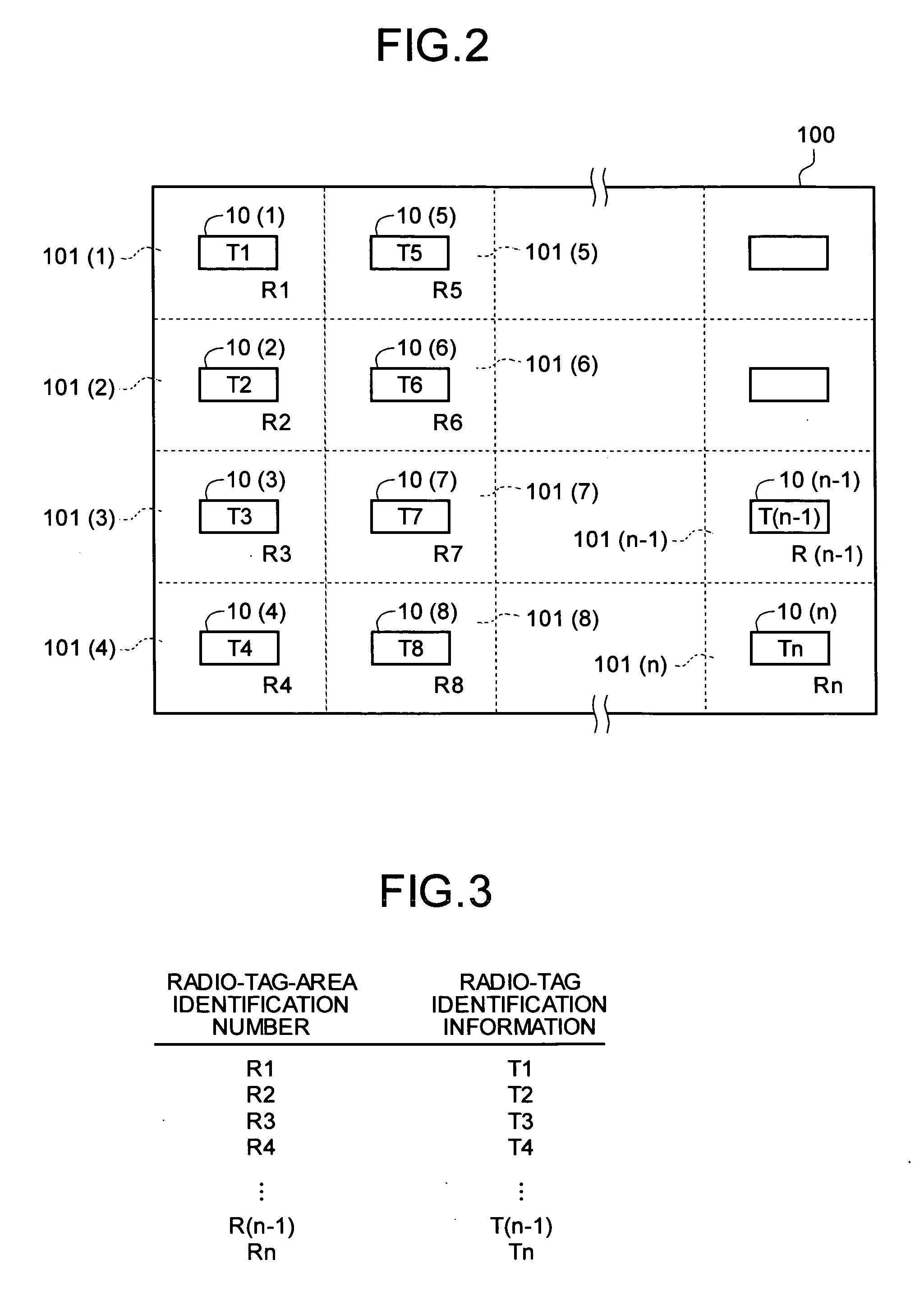
[0009] According to the present invention, when there is an object or the like on a radio tag, the radio tag cannot receive a read request from a radio tag reader due to shadowing by the object, and therefore the presence or absence of an object in a radio tag area can be determined. The radio tag reader and the radio tag communicate with each other via radio, and a communication area can be optionally enlarged or narrowed by changing an output of a radio communication unit. Accordingly, the presence or absence of objects or the like on a plurality of radio tag areas can be obtained simultaneously and quickly. Since the radio tag reader need not be moved, a moving unit is not required, and the system can be configured at low cost. Further, the present invention can be introduced to an existing system, and even in this case, a wide range can be managed at low cost.

Problems solved by technology

In this system, however, although the total number of vehicles in the parking lot can be managed, it cannot be ascertained which specific place is empty.
In this method, however, because a plurality of vehicles cannot be detected with one infrared sensor, due to the physical directional characteristics of infrared rays, many infrared sensors need to be installed, thereby increasing cost.
If only a few sensors are installed to reduce the cost, all the parking places cannot be covered.

Method used


Image

  • Place-Status Management System, Radio Tag Reader, and Managing Apparatus
  • Place-Status Management System, Radio Tag Reader, and Managing Apparatus
  • Place-Status Management System, Radio Tag Reader, and Managing Apparatus

Examples


first embodiment

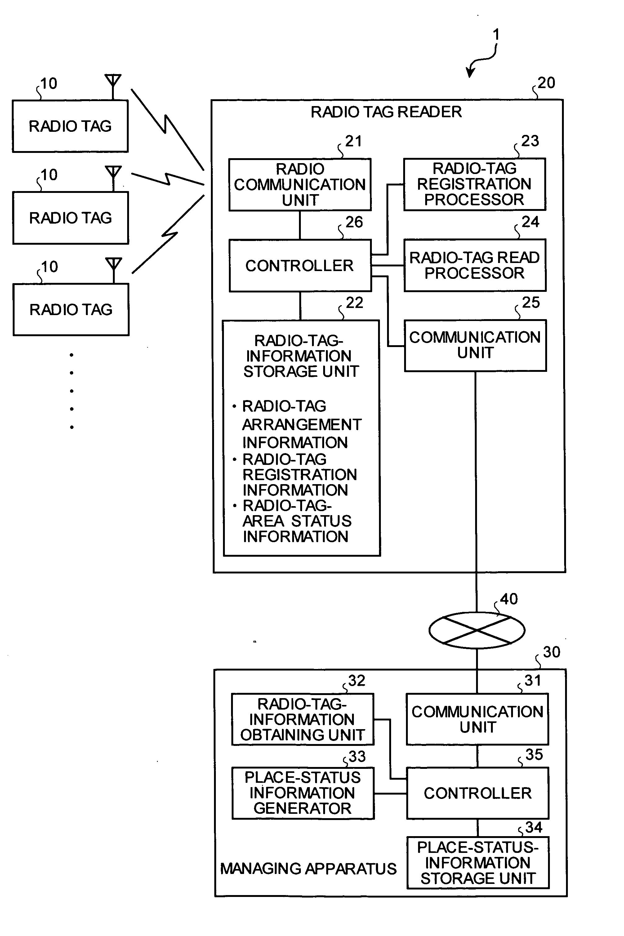
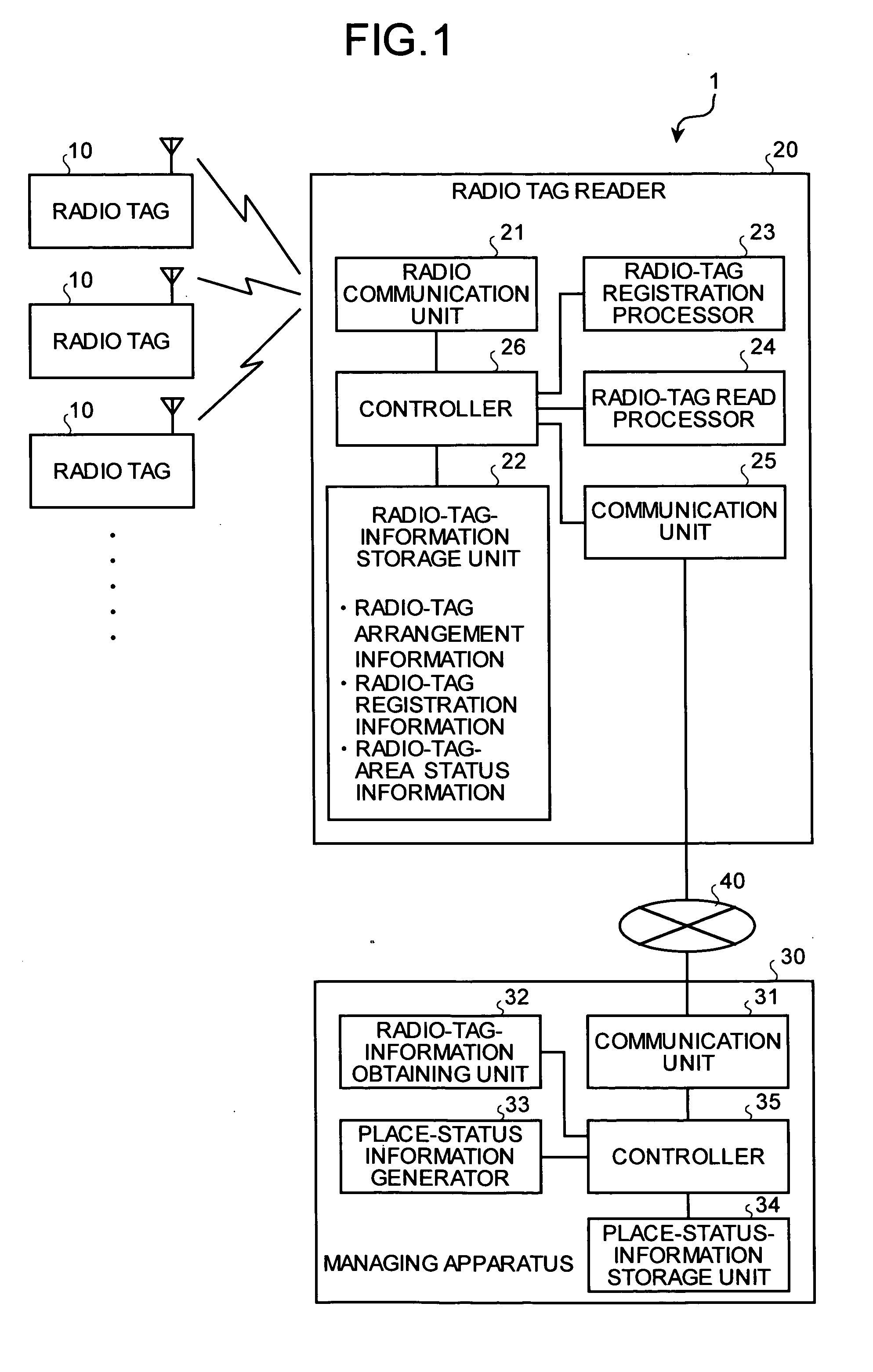
[0068]FIG. 1 is a block diagram of a place-status management system according to an embodiment of the present invention. A place-status management system 1 includes a plurality of radio tags (radio frequency identification (RFID)) 10 arranged at predetermined positions in a place managed by the system (hereinafter, “management area”), a radio tag reader 20 that communicates with the radio tags 10, and a managing apparatus 30 that generates place information indicating presence of an object or a person at the predetermined position obtained from the radio tag reader 20 to manage the management area. The radio tag reader 20 and the managing apparatus 30 are connected via a communication line 40 such as a network.

[0069] The radio tag 10 includes, though not shown, a communication unit that performs radio communication with the radio tag reader 20, a storage unit that stores predetermined information relating to the radio tags 10, including identification information for identifying th...

second embodiment

[0107] In the first embodiment, an outline of the place-status management system has been explained. In a second embodiment, an example in which the place-status management system is used for managing a parking lot is explained as a specific embodiment.

[0108]FIG. 16 schematically depicts a configuration when the place-status management system of the present invention is applied to management of a parking lot. FIG. 17 schematically depicts arrangement of the radio tag reader and the radio tags in the parking lot. A place-status management system 1a includes a parking lot 100a as a management area, in which a plurality of radio tag areas 101 as a space for parking a vehicle are provided. The place-status management system 1a further includes the radio tag 10 buried in each radio tag area 101, a plurality of radio tag readers 20 that communicate with the radio tags 10, an entrance gate 51 and an exit gate 52 provided at a gateway of the parking lot 100a, a repeater 301 that collects i...

third embodiment

[0118] In a third embodiment, the place-status management system explained in the first embodiment is applied to waiting time management of attractions such as in an amusement park. FIG. 21 depicts a configuration of a place-status management system according to the third embodiment, and depicts a system configuration when waiting time is managed from a length of a queue formed by people waiting to enter a certain amusement facility.

[0119] The radio tags 10(1) to tag 10(4) are buried at predetermined positions of a path 131 for sequentially guiding people waiting to enter an attraction 130. In an example shown in FIG. 21, the radio tags are buried at positions of turning points of the path 131. The radio tag readers 20(1) to 20(3) are provided at positions where these radio tags 10(1) to 10(4) can be read. The communication areas 102(1) to 102(3) of the radio tag readers 20(1) to 20(3) are areas enclosed by dotted line in FIG. 21. Display apparatuses 140(1) to 140(4) such as a liqu...


PUM


Abstract

A radio tag is arranged in each of a plurality of radio tag areas. The radio tag areas can be parking lots. A radio tag reader is configured to perform radio communications with the radio tags. The radio tag reader performs radio communications with each radio tag and based on the radio communication determines whether an object, which can be a vehicle, is present in the radio tag area corresponding to the radio tag.

Description

TECHNICAL FIELD [0001] The present invention relates to a place-status management system that detects whether there is an object or a person in a predetermined place, such as a parking lot or a meeting place, to manage the status of the predetermined place, and a radio tag reader and a managing apparatus used for the place-status management system. BACKGROUND ART [0002] A parking lot management system is an example where a system that manages the number of objects present in a predetermined place is applied. In a parking lot management system, the number of vehicles that can enter the parking lot is managed by counting the number of vehicles entering through an entrance gate and the number of vehicles leaving through an exit gate. A control is provided so that vehicles of a number larger than the number of vehicles that can be park in the parking lot do not enter the parking lot. In this system, however, although the total number of vehicles in the parking lot can be managed, it can...

Claims


Application Information

Patent Timeline
IPC IPC(8): G08B5/22G01S13/46G06K17/00G06Q10/00G06Q50/00G06Q50/10G08G1/14
CPCG08G1/14
Inventor NAGAI, YUKIMASASUGA, HIROYOSHI
Owner MITSUBISHI ELECTRIC CORP
Learn More