
Automatic leveling suspension system for luminaires

a suspension system and lighting fixture technology, applied in the field of automatic leveling suspension system of lighting fixture, can solve the problems of time-consuming process and may require additional adjustments in the installation process, and achieve the effect of convenient and quick suspension

Inactive Publication Date: 2007-10-25
HUBBELL INC
View PDF27 Cites 79 Cited by
  • Summary
  • Abstract
  • Description
  • Claims
  • Application Information

AI Technical Summary

Benefits of technology

[0005] Accordingly, an object of the present invention is to provide a lighting fixture that is easily and quickly suspended in a level configuration from a ceiling or beam.

Problems solved by technology

However, this is a time consuming process.
However, the installation process may require additional adjustments by hand because the sides of the cable loop can hang up on the sides of the sheet metal tabs receiving the loops and hold the fixture at an angle rather than horizontal, i.e., level to the ground.

Method used


Image

  • Automatic leveling suspension system for luminaires
  • Automatic leveling suspension system for luminaires
  • Automatic leveling suspension system for luminaires

Examples


Embodiment Construction

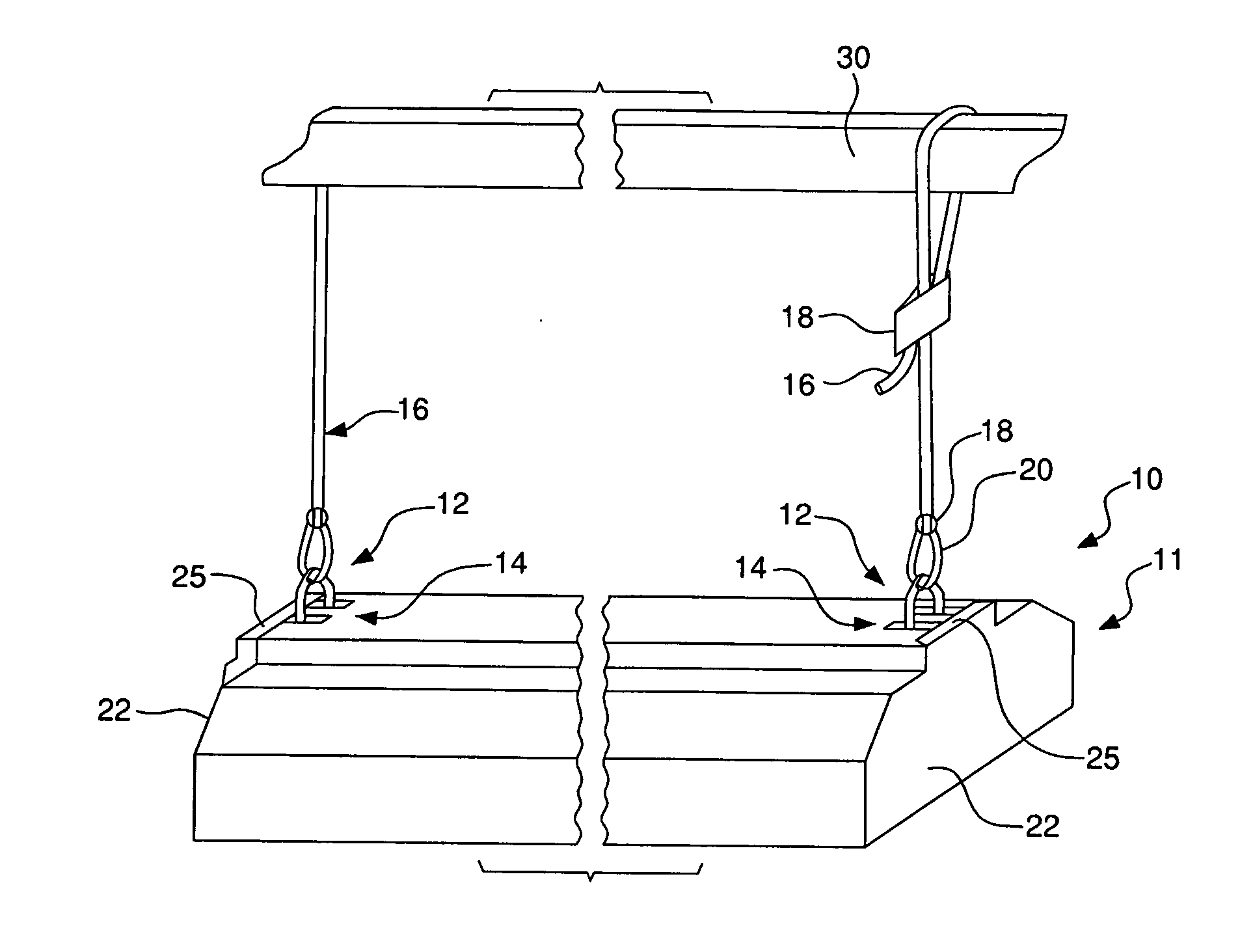
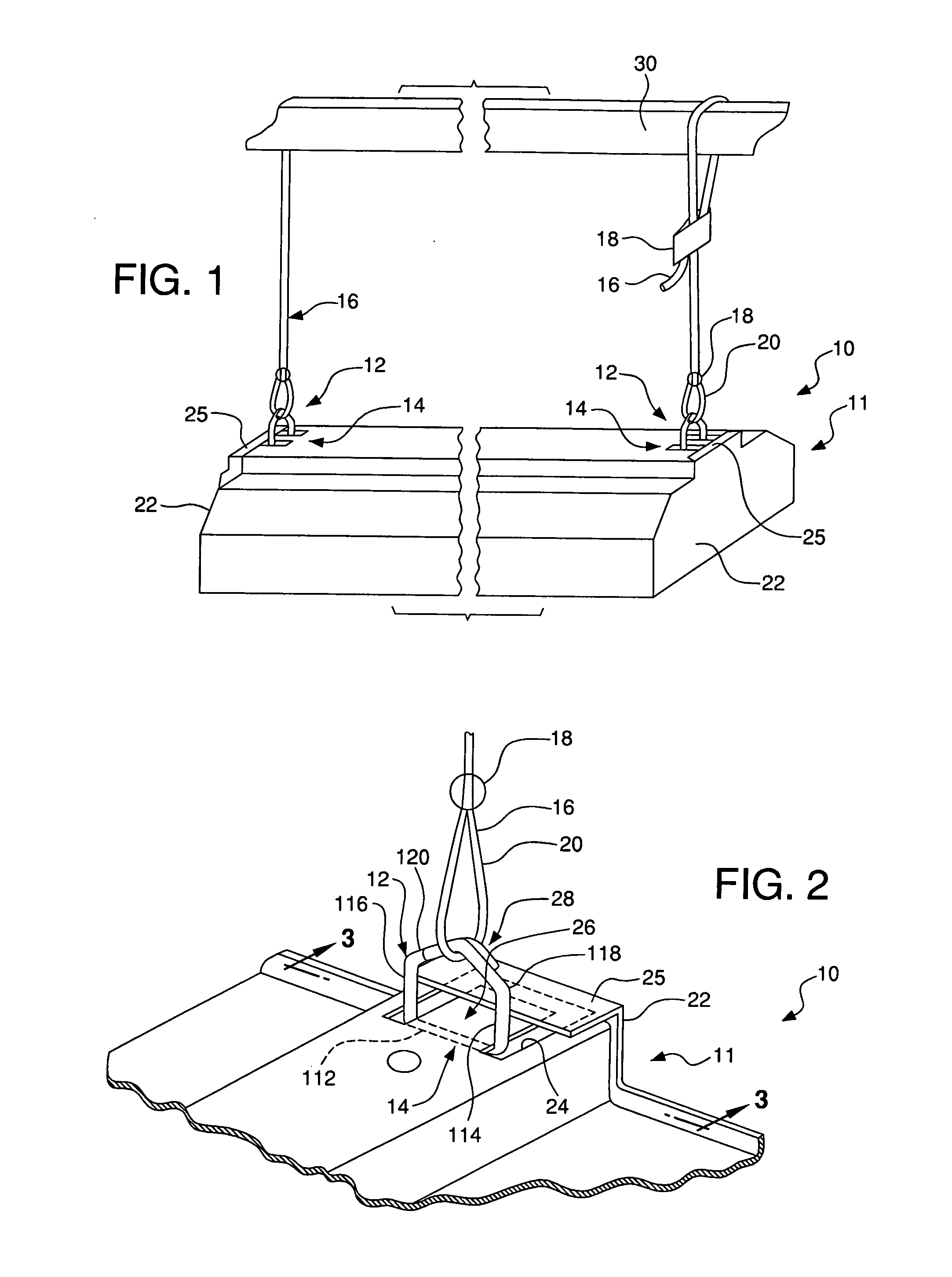
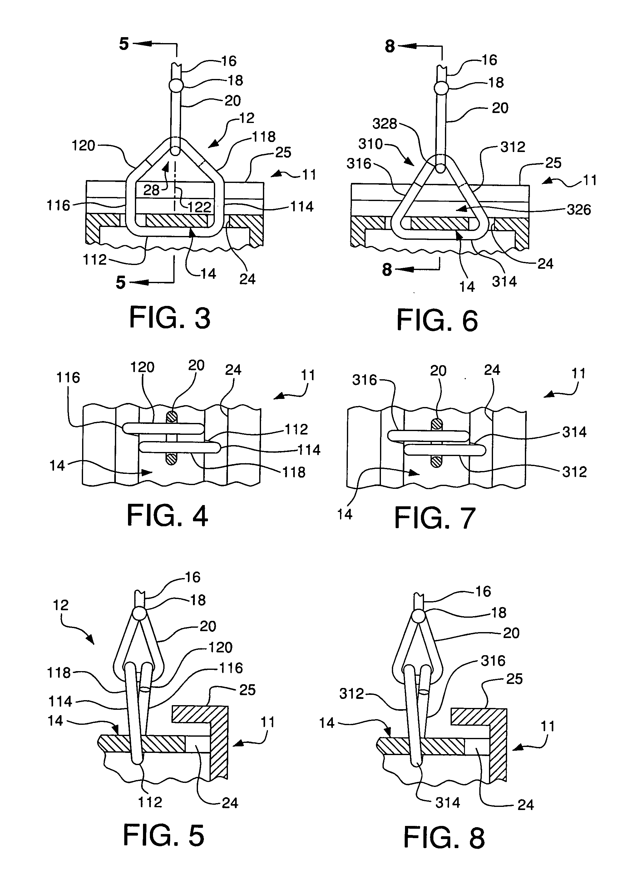
[0027] Referring to FIGS. 1-5, a suspension assembly 10 for a lighting fixture 11, in accordance with the present invention, includes a hanger 12 and a support member 14 that extends outwardly and horizontally towards the ends 22 of the lighting fixture 11. The support members or tongues 14 are planar and located on the upper planar surface of the lighting fixture 11 and are positioned parallel to the bottom of the lighting fixture 11. Tongues 14 are substantially rectangular in shape and are surrounded by a U-shaped recess 24 at the three sides closest to the ends 22 of the lighting fixture 11 with a cover plate 25 extending horizontally and inwardly from each of the ends 22 and over parts of the tongue 14 and recess 24. The tongues 14 extend along the horizontal center of gravity axis of the fixture.

[0028] As illustrated in FIG. 1, the lighting fixture 11 is suspended from the ceiling with cables 16, looped around a joist 30 at one end of cable 16 and attached to the lighting fix...


PUM


Abstract

A mechanism and method for automatically leveling an assembly, such as a lighting fixture, suspended from a cable having a loop, the assembly having a support member. The mechanism comprises a hanger having an opening for receiving the support member of the assembly therein. The hanger includes a plurality of sides and at least one interior downwardly facing surface for engaging the cable loop through the hanger. The hanger is inserted through a tongue on the suspension assembly and the cable loop is inserted into the hanger and engages the interior downwardly facing surface, thereby automatically leveling and suspending the assembly from the ceiling.

Description

FIELD OF THE INVENTION [0001] The present invention relates to a leveling hanger for suspending a lighting fixture. More specifically, the invention relates to a suspension system for automatically leveling a lighting fixture suspended from cables coupled to the ceiling of a building. Still more particularly, the present invention includes a hanger having an upwardly facing surface engaging a support member on the fixture and a downwardly facing surface engaging the loop of a suspension cable, the hanger being substantially perpendicular to the fixture and fixedly receiving the loop in the center of the hanger to maintain the fixture in a level configuration. BACKGROUND OF THE INVENTION [0002] Conventional lighting fixtures for retail and industrial applications are often installed or mounted by being suspended from a ceiling. Typically, fixture ends are removed allowing access to cables extending through the housing top wall, and the cable ends are fastened to the housing. Subseque...

Claims


Application Information

Patent Timeline
IPC IPC(8): B42F13/00
CPCF21S8/06F21V21/112F21V21/104
Inventor BROWN, RAYMOND A.BRONDT, GARY W.
Owner HUBBELL INC
Learn More