
Reel

a reel and reel plate technology, applied in the field of reels, can solve the problems of deteriorating the precision of the gear on the drive device side with the gear on the reel side, and it is difficult to ensure the planarity of the reel pla

Inactive Publication Date: 2007-10-25
FUJIFILM CORP
View PDF7 Cites 2 Cited by
  • Summary
  • Abstract
  • Description
  • Claims
  • Application Information

AI Technical Summary

Benefits of technology

[0009]A reel that can ensure the planarity of the reel plate after insert molding is provided according to the present invention.

Problems solved by technology

However, since the reel plate is integrated to the hub by insert molding, deformation of the reel plate body may be generated by the extrusion pressure of the resin during molding or the shrinkage stress or the like of the resin after molding, and it is sometimes difficult to ensure the planarity of the reel plate.
Therefore, sometimes the meshing precision deteriorates of the gear on the drive device side with the gear on the reel side.

Method used


Image

  • Reel
  • Reel
  • Reel

Examples


Embodiment Construction

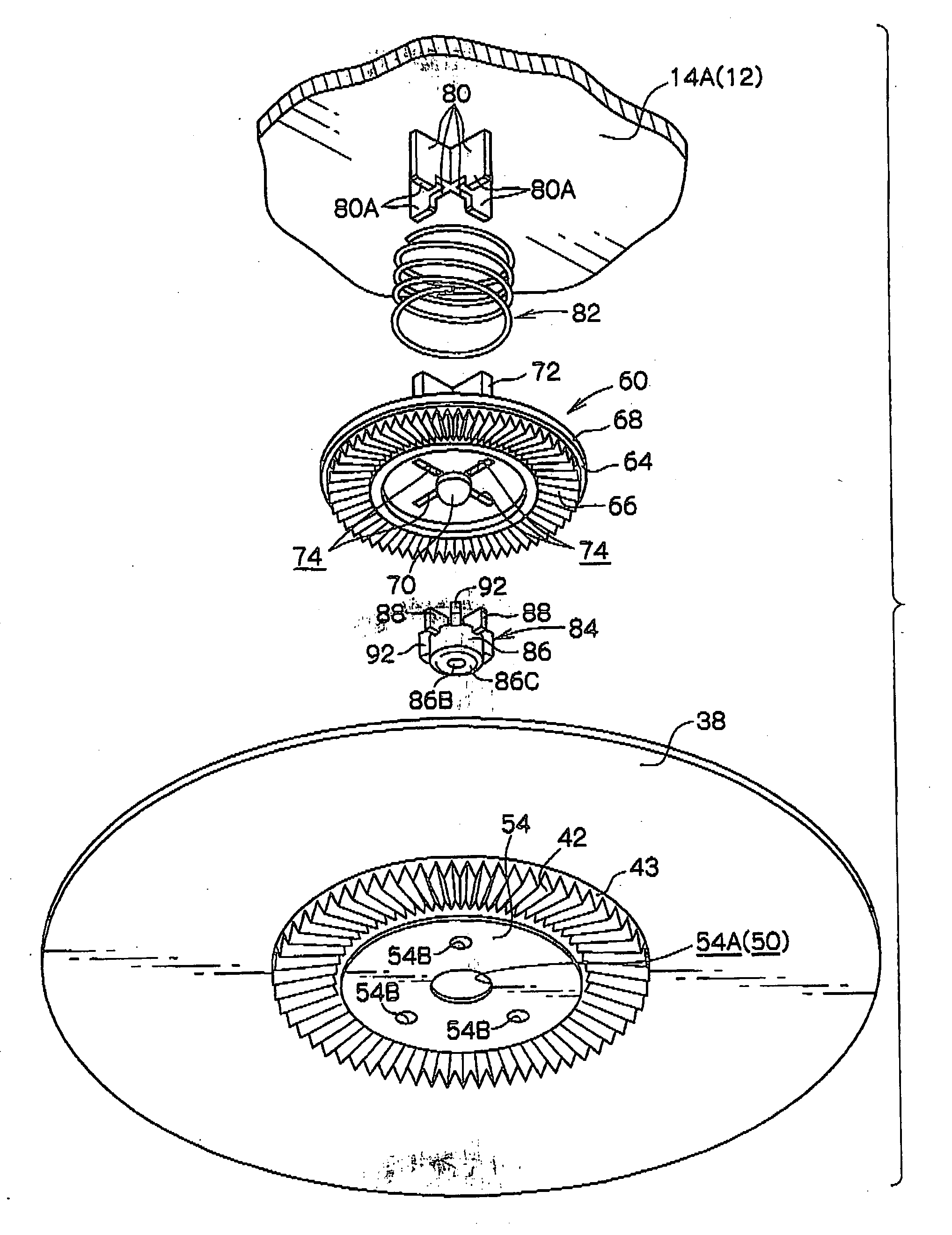
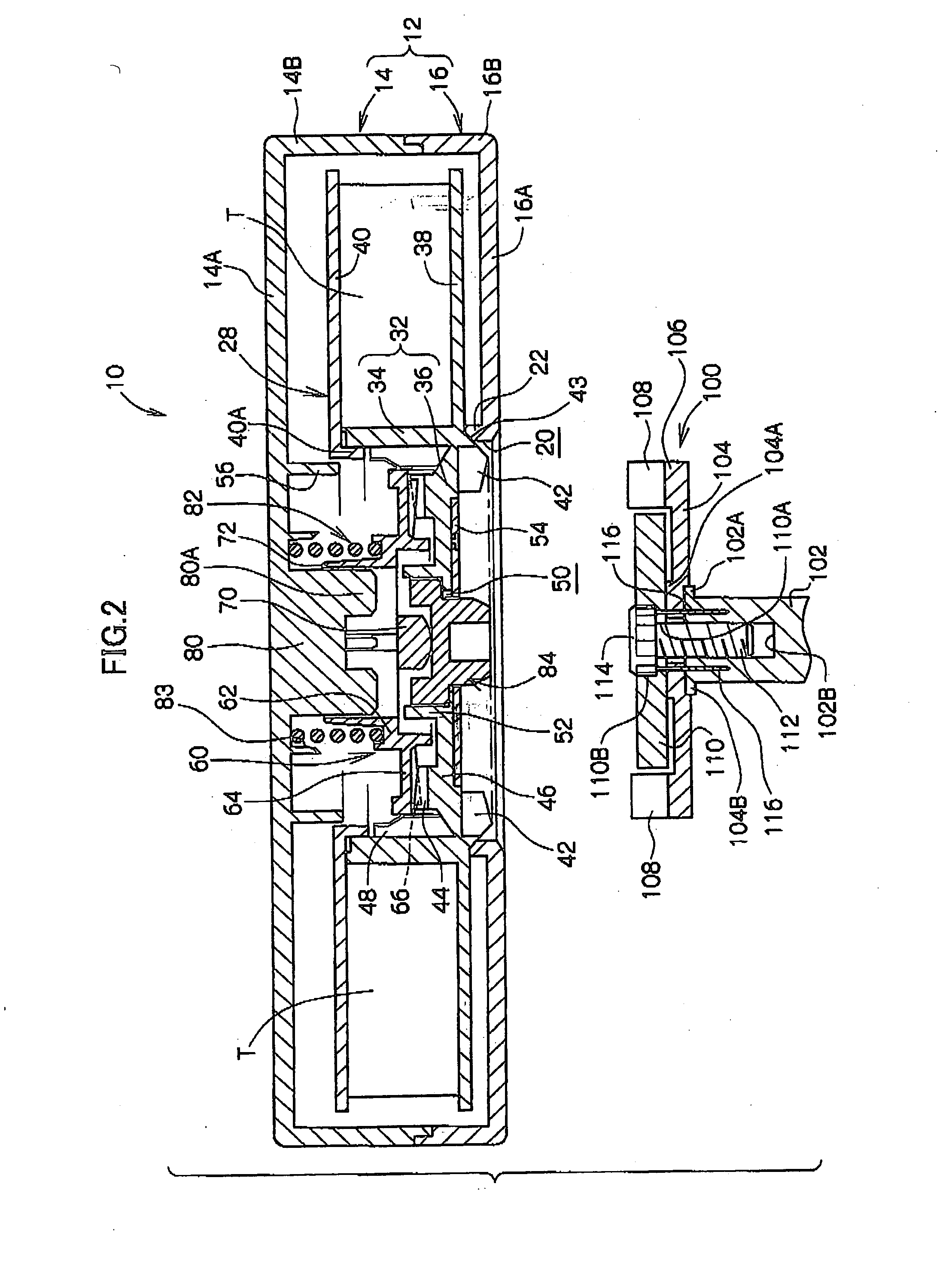
[0023]Herebelow, an exemplary embodiment of a drive device according to the present invention will be described in detail with reference to the drawings.

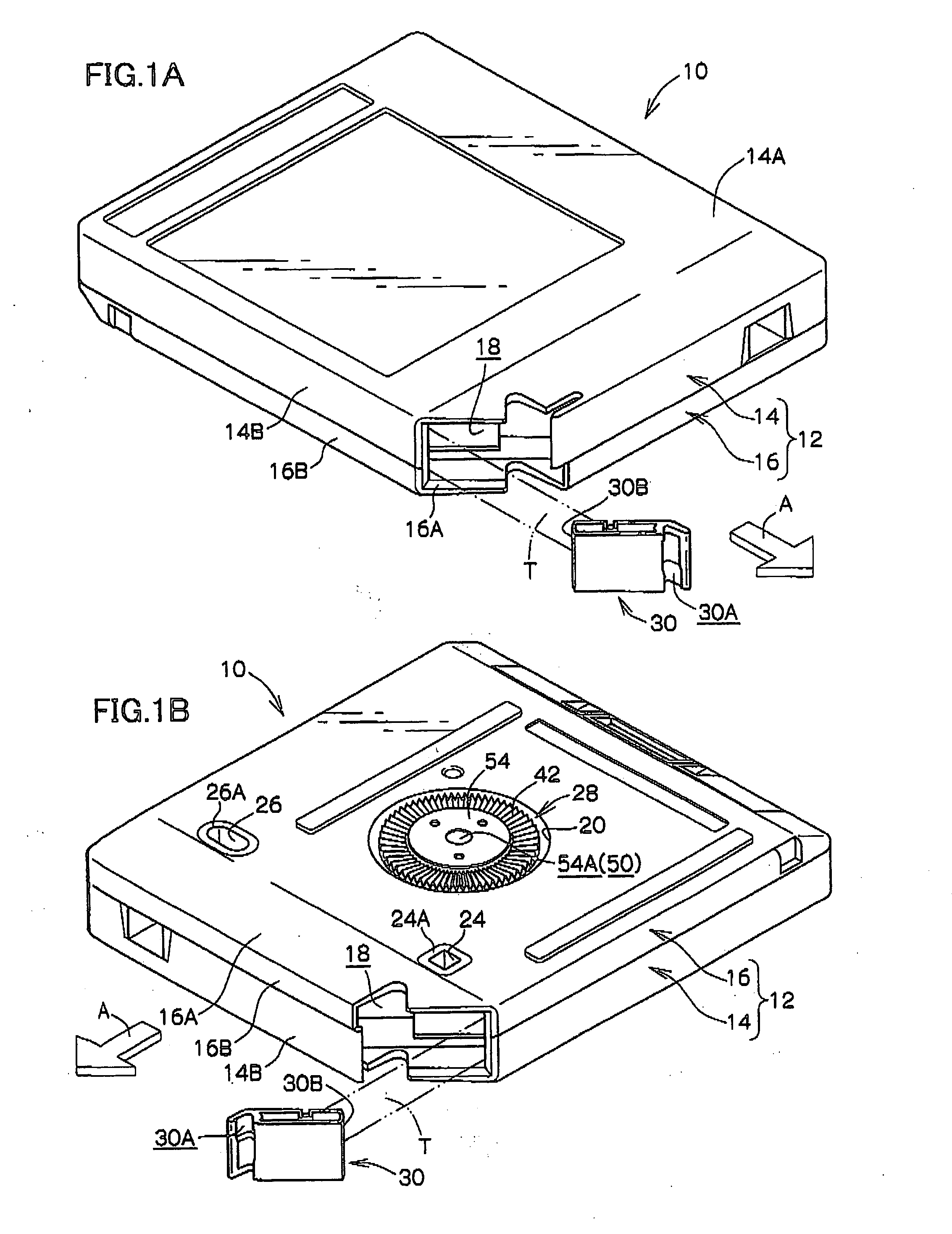
[0024]First, a recording tape cartridge (magnetic tape cartridge) 10 which can be loaded into a drive device will be described. Note that, for convenience of explanation, the direction of loading the recording tape cartridge 10 into the drive device of is denoted by arrow A, and this direction of arrow A is defined as the forward direction (front side) of the recording tape cartridge 10.

[0025]As shown in FIGS. 1A through 3, the recording tape cartridge 10 has a case 12. The case 12 is structured by an upper case 14 and a lower case 16 being joined together. Specifically, the upper case 14 is structured such that a substantially frame-shaped peripheral wall 14B extends down along the outer edge of a ceiling plate 14A that is substantially rectangular in plan view. The lower case 16 is structured such that a peripheral wall 16B stands...


PUM


Abstract

A reel in which the planarity of a reel plate after insert molding may be ensured. The reel plate is formed into a concave shape, and by insert molding, the reel plate is made substantially flat. When a reel plate is insert molded, the reel plate is deformed in the direction to protrude in the direction to the outside of the reel by shrinkage stress of resin after molding. Therefore, by concaving the reel plate in advance into a concave shape, even if the reel plate is protruded by the shrinkage stress of the resin after insert molding, the amount of protruding may be absorbed by the amount of concaving, and the shape of the reel plate may be made substantially flat. That is to say, the planarity of the reel plate may be obtained. By doing so, the meshing of the reel gear that surrounds the reel plate with the drive gear on the rotation shaft side of the drive device may be improved.

Description

CROSS-REFERENCE TO RELATED APPLICATION[0001]This application claims priority under 35 U.S.C 119 from Japanese Patent Application No. 2006-119601, the disclosure of which is incorporated by reference herein.BACKGROUND OF THE INVENTION[0002]1. Field of the Invention[0003]The present invention relates to a reel for winding recording tape, such as magnetic tape or the like, thereon.[0004]2. Description of the Related Art[0005]Conventionally known are, recording tape cartridges with a storage reel, on which is wound magnetic tape, accommodated in a case, as disclosed, for example, in Japanese Patent Application Laid-Open (JP-A) No. 2005-259245. The reel is provided with a hub, configuring an axial central portion of the reel, for winding magnetic tape on the external peripheral surface thereof, and a top flange and a bottom flange that extend outside from the hub in the radial direction from respective ends in the axial direction.[0006]Conventionally known are recording tape cartridges i...

Claims


Application Information

Patent Timeline
Patent Type & Authority Applications(United States)
IPC IPC(8): B65H75/14
CPCG11B15/32G11B23/107G11B23/044G11B23/037
Inventor ONMORI, SHOZO
Owner FUJIFILM CORP
Learn More