
Drainage pipe slope measuring device

a technology of drain pipe slope and measuring device, which is applied in the direction of sewer pipelines, instruments, mechanical equipment, etc., can solve the problems of difficult to see the level vial, the flat flange is difficult to maintain against the body of the drain pipe, and the traditional carpenter's bubble level is not well adapted for determining, so as to achieve a further visual contrast for the user

Inactive Publication Date: 2007-10-25
PEAK B DAVID +3
View PDF22 Cites 25 Cited by
  • Summary
  • Abstract
  • Description
  • Claims
  • Application Information

AI Technical Summary

Benefits of technology

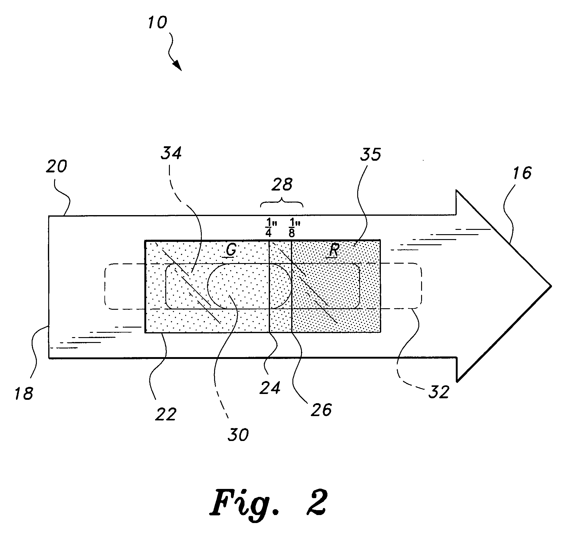
[0014]Further, the opening is defined by first and second longitudinally opposed side edges, and the at least partially transparent or translucent material forming the vial has first and second colors associated therewith. A first region of the vial extending between the first side edge and the indicia is colored with the first color, and a second region of the vial extending between the indicia and the second side edge is colored with the second color, thus providing further visual contrast to the user.

Problems solved by technology

Further, drain pipes may be installed in locations that may be difficult to reach, such as in ditches, under crawl spaces, etc.
The traditional carpenter's bubble level is not well adapted for determining the compliance of drainage pipe installations with the mandated slope.
The flat flanges are difficult to maintain against the body of the drain pipe, which is usually cylindrical.
When looking down into a drain pipe installed in a ditch, or looking at a drain pipe installed in a crawl space from the side, it can be difficult to see the level's vial.
Even when the carpenter's level has a third vial that is angularly adjustable, the angle must be estimated and the meniscus is relatively short, leading to inaccurate measurements.
While various devices have been proposed to remedy at least some of these problems, none have been found entirely satisfactory, and none is in common use.
As a result, quite often instruments are not used to measure the slope of drainage pipes.

Method used


Image

  • Drainage pipe slope measuring device
  • Drainage pipe slope measuring device
  • Drainage pipe slope measuring device

Examples


Embodiment Construction

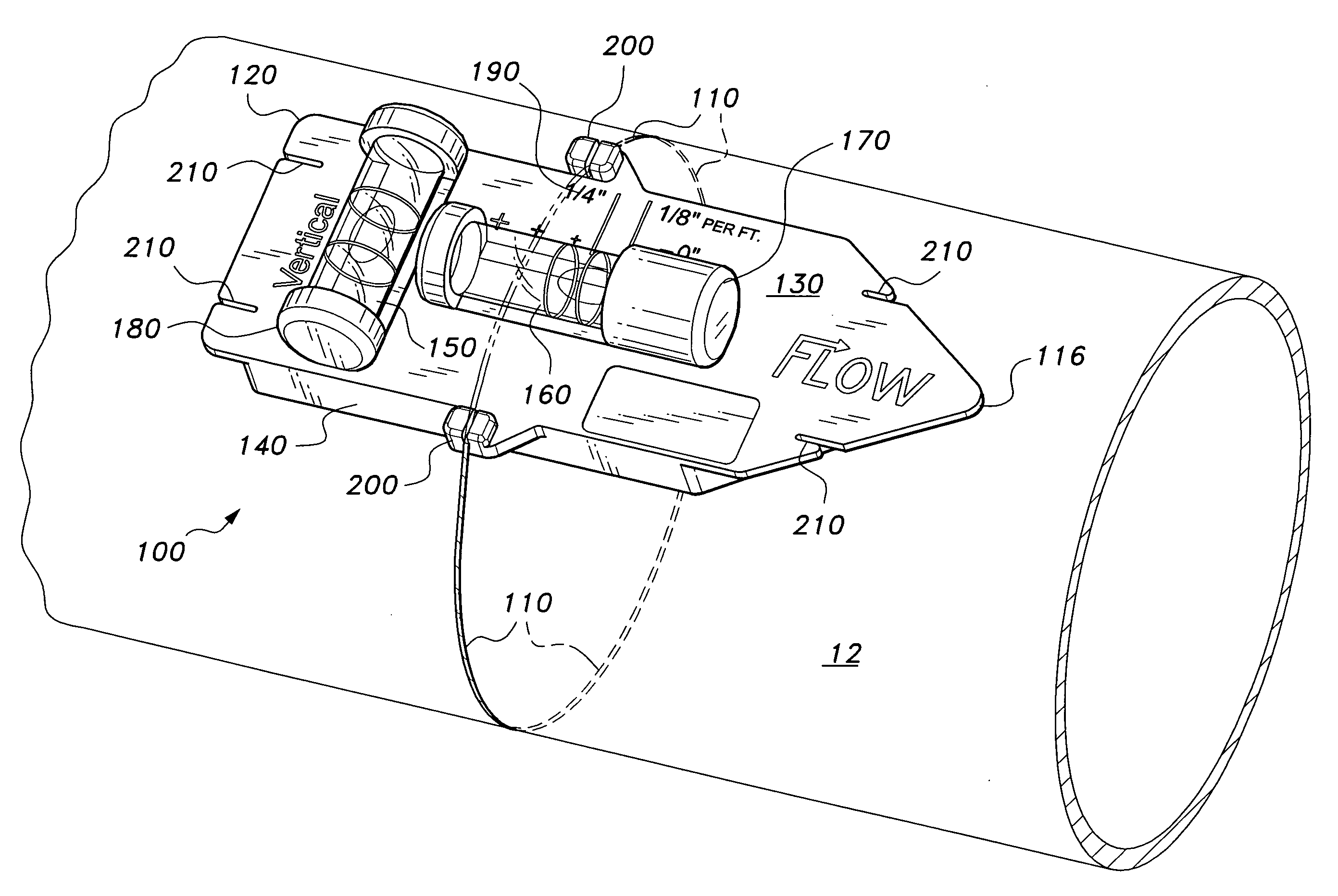
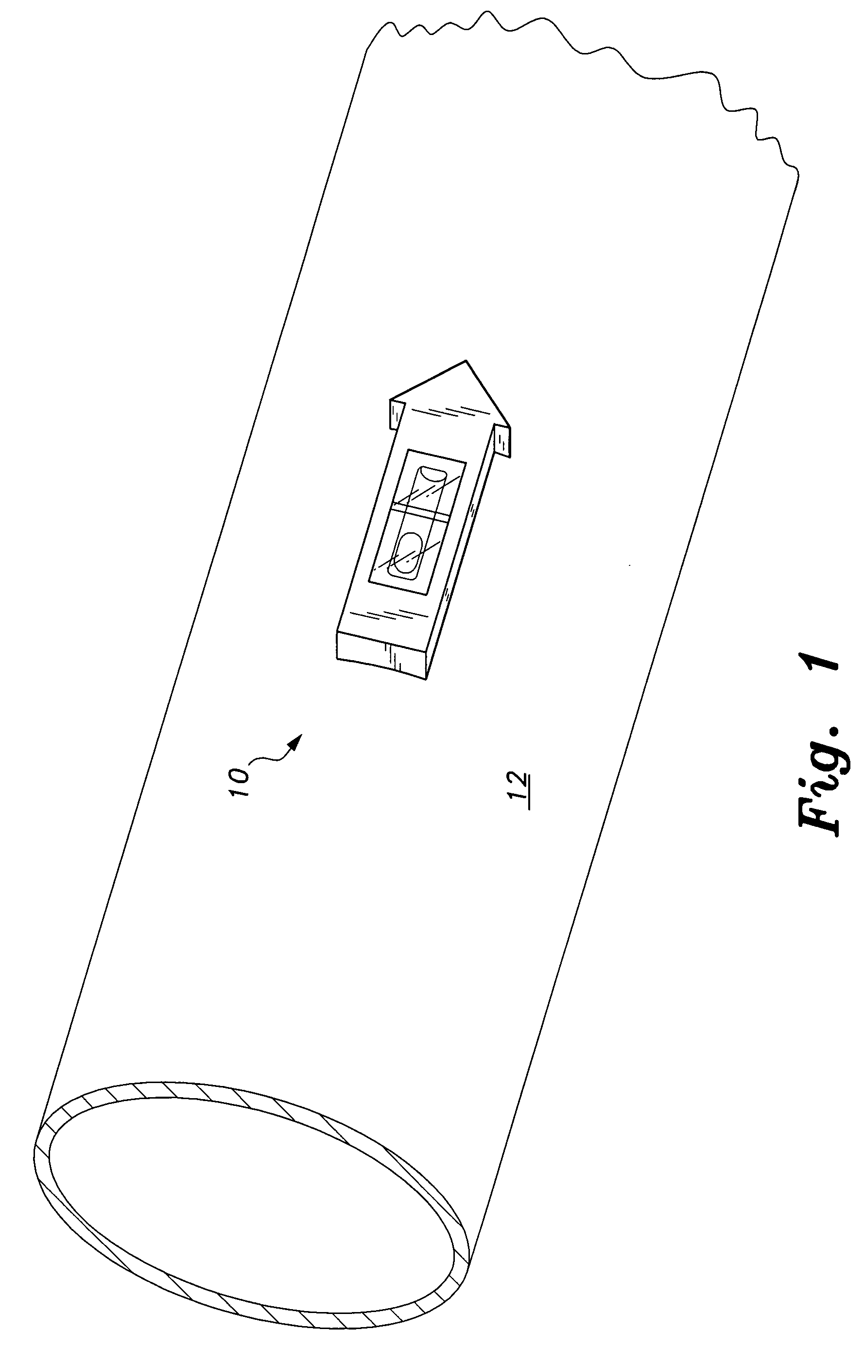
[0022]The present invention, a first embodiment of which is illustrated in FIGS. 1-3, is directed to a drainage pipe slope measuring device, designated generally as 10 in the drawings. Drainage pipes, such as drainage pipe 12, shown in FIG. 1, are typically required by building codes and regulations to have a particular angular declination with respect to the horizontal. For example, a drainage pipe may be required under residential or commercial building codes to have a declining slope of one-quarter to one-eighth of an inch fall (in the vertical direction) per one foot of drainage piping. The particular angular positioning is required to allow the waste water and material flowing through pipe 12 to efficiently move through the pipe under the force of gravity.

[0023]The drainage pipe slope measuring device 10 may be mounted to the exterior of a drainage pipe, such as pipe 12, to provide the user with a visual indication of whether the slope of the pipe 12 satisfies the particular co...


PUM


Abstract

The drainage pipe slope measuring device includes a housing having an upper surface and a lower surface. The upper surface has an opening formed therethrough, the lower surface preferably having a substantially concave or arcuate cross-sectional contour adapted for flush mounting against the drainage pipe. A spirit level vial is mounted within the housing and is positioned adjacent the opening. The vial is preferably formed from at least partially transparent or translucent material and is adapted for containing a liquid and a gas bubble. Indicia is formed on the container and is visible through the opening so that, when the housing is mounted on the drainage pipe, a position of the gas bubble with respect to the indicia provides the user with a visual indication of the slope of the drainage pipe. The vial is preferably divided into separately colored regions to provide the user with further visual contrast.

Description

CROSS-REFERENCE TO RELATED APPLICATION[0001]This application claims the benefit of U.S. Provisional Patent Application Ser. No. 60 / 793,632, filed Apr. 21, 2006.BACKGROUND OF THE INVENTION[0002]1. Field of the Invention[0003]The present invention relates to level indicator devices for use by plumbers, carpenters and electricians, and particularly to a drainage pipe slope measuring device for ensuring that drainage pipes meet the minimum slope required by building codes.[0004]2. Description of the Related Art[0005]Drain-waste pipes form an important part of any plumbing installation. Local ordinances and building codes generally require that drain pipes be installed with a slight pitch or downward slope leading away from the plumbing installation to help prevent waste and drain water from backing up into the house or building plumbing system. The angle of declination may vary according to the diameter of the drain pipe. A common requirement is that a drain or sewer line three inches o...

Claims


Application Information

Patent Timeline
IPC IPC(8): F16L55/00
CPCE03F3/06E03F7/12F16L1/06E03C2001/028G01C15/00E03C1/122G01C9/18
Inventor PEAK, B. DAVIDBRANSCOMB, DAVIDHOPKINS, KENBOWDEN, WES
Owner PEAK B DAVID
Learn More